Flex Pro Laser: No Light, Weak Cut, Distorted
← All Flex Pro troubleshooting
The protective window is dirty or damaged, cutting weakens, the laser emits no light, or engraved patterns look poor, distorted, reversed, or skewed.
Disconnect power before disassembly or electrical testing. Turn off the engraving machine before removing the laser and disconnecting its cable, or removing and reinserting the TF card. Do not turn off the machine or remove the TF card during a firmware update.
¶ Dirty or Damaged Lens
What you see: Dirty or Damaged Laser Module Lens
Refer to the Flex Pro laser module maintenance video and follow the steps below.
1) Dirty Window
The laser module's protective window must be cleaned if it becomes dirty. Otherwise, laser power may be significantly reduced, and the protective window may even become damaged.
① Cleaning Tools
- Lint-free cloth.
- Absolute ethanol (a purity of 99% or higher is recommended).
② Cleaning Procedure
- Remove the laser module
Turn off the engraver, loosen the fixing screws on the side of the laser module, remove the laser module, and disconnect its cable.
- Clean the window
Apply a small amount of absolute ethanol to a lint-free cloth. Wipe the lens gently in a spiral motion from the center outward, moving in a single direction. Avoid rubbing back and forth, as this may cause scratches.
2) Damaged Protective Window
- 7W laser module: The protective window is not replaceable. If it is damaged, the entire laser module must be replaced.
- 12W laser module: The protective window can be replaced separately.
To prevent damage caused by contaminants burning onto the protective window or other abnormalities, refer to the “Laser Module Maintenance” section and clean the window regularly to keep its surface clean.
3) Contact Customer Support
If you encounter a problem during troubleshooting that you cannot resolve yourself, please provide the following information to Customer Support:
- Clear photos of the dirty or damaged area.
- A photo of the laser module's laser-engraved code, as shown in Figure 43.
4) Component Replacement Reference
- If the laser module needs to be replaced, refer to the Flex Pro laser module replacement video.
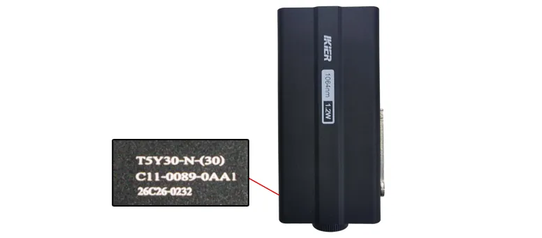
Figure 43
¶ Weaker Cutting Power
What you see: The Laser Cutting Performance Has Significantly Decreased
Please follow the steps below to troubleshoot the issue.
1) Check the Focusing Distance
After placing the material, adjust the laser focusing distance. Swing the fixed-focus rod on the side of the laser module, loosen the laser module fixing screws, and lower the laser module until the tip of the rod touches the material surface, as shown in Figure 44. Then retighten the fixing screws and fold the rod back.
Note
The IR laser is highly sensitive to the focusing distance. Since IR light is invisible, engraving sparks may not be visible if the focusing distance is incorrect.
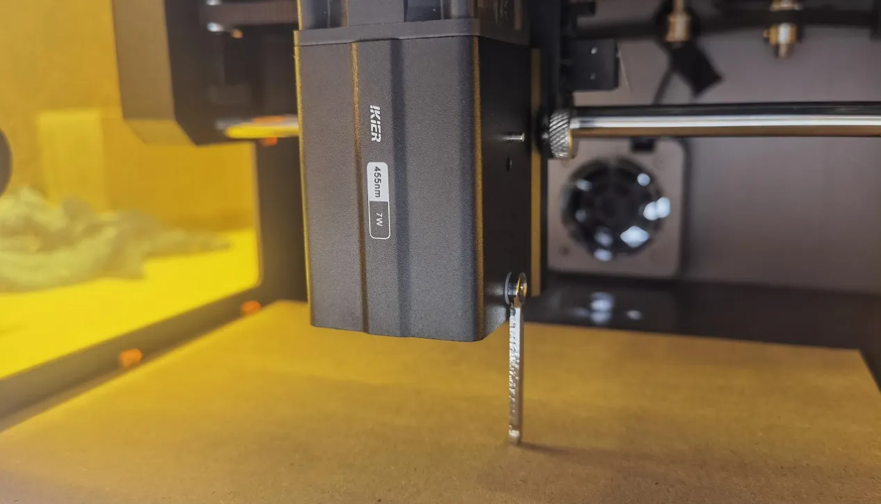
Figure 44
2) Check the Protective Window
A dirty or damaged protective window can significantly reduce laser output power. Refer to the “Dirty or Damaged Laser Module Protective Window” section for instructions.
3) Check the Software Parameters
Different materials require different processing parameters. Refer to the parameter table to verify that the power, speed, and speed units are set correctly.
Note
How to Access the Parameter Table
- Scan the QR code on the machine.
- Check the included USB drive.
- Contact Customer Support.
- Some materials have corresponding preset parameters in AtomStack Studio.
4) Check the Material Batch
Differences in manufacturing processes between material batches may affect cutting performance. We recommend the following:
- Compare cutting results using materials from the same batch.
- Cut A4 paper to determine whether the laser output power has significantly decreased.
Recommended settings for cutting A4 paper:
- Flex Pro 12W: 60% power, 2000 mm/min speed.
- Flex Pro 7W: 100% power, 1300 mm/min speed.
5) Check the Maximum S-Value in LightBurn
The maximum S-value must remain set to 1000, as shown in Figure 45. Do not change this value, as doing so may affect laser power and service life.
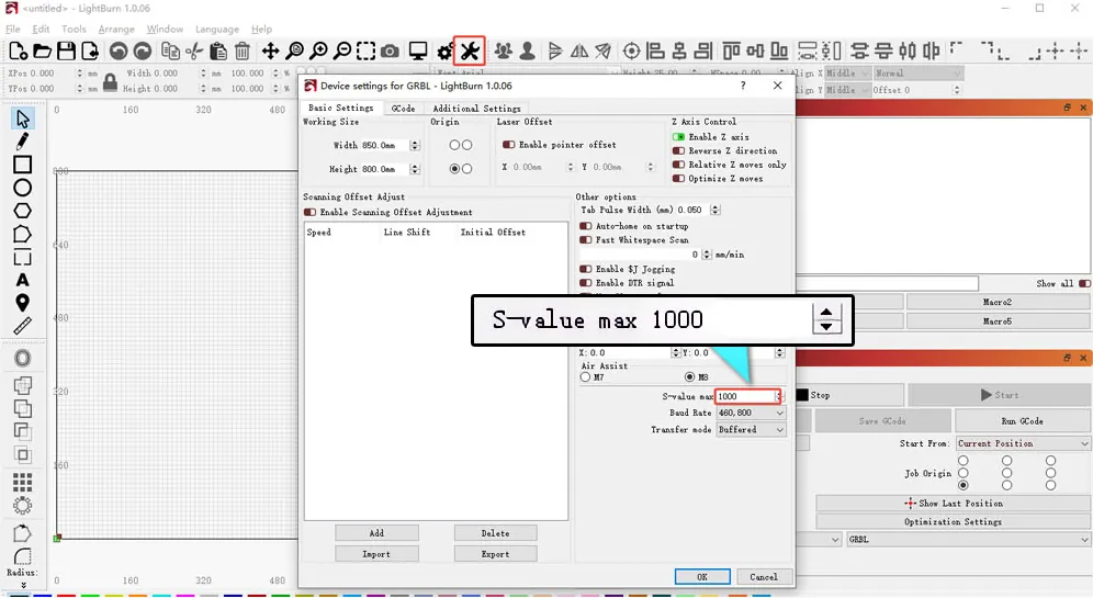
Figure 45
6) Check the Power Supply Output
Insufficient voltage or current directly affects laser output power.
- Measure the power adapter output: Set the multimeter to DC voltage mode and check whether the adapter outputs 24V. If an ammeter is available, measure whether the adapter can provide an output current of up to 3A.
- Measure the laser module cable: Disconnect the laser module cable. Run a cutting program at 100% power and a speed of 1 mm/min. Set the multimeter to DC voltage mode and check whether the voltage is 24V between pins 1 and 2 and 5V between pins 2 and 3, as shown in Figure 46. Refer to the Flex Pro voltage measurement video for guidance.
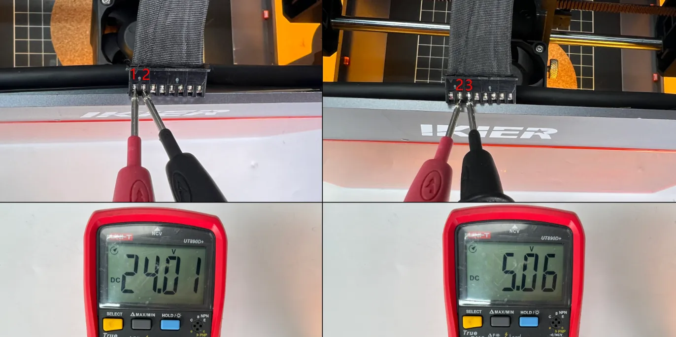
Figure 46
7) Contact Customer Support
If you encounter a problem during troubleshooting that you cannot resolve yourself, or if you are unable to determine the cause of the fault, please provide the following information to Customer Support.
- A cutting video: Clearly show the power and speed settings, material thickness, cutting process, and final result.
- A description of the troubleshooting steps performed: If voltage measurements were taken, include the measurement results.
- Photos of the laser module protective window: Ensure the photos are clear.
- A photo of the laser module's laser-engraved code, as shown in Figure 47.
Figure 47
8) Component Replacement Reference
- If the laser module needs to be replaced, refer to the Flex Pro laser module replacement video.
¶ Moves but No Light
What you see: Laser head moves but no Laser Output
Follow the steps below to troubleshoot the issue one by one:
1) Check the Software Settings
Different materials require corresponding processing parameters. Refer to the parameter table to confirm that the set power, speed, and speed unit are correct.
How to View the Parameter Table:
- Scan the QR code on the machine.
- Check the included USB flash drive.
- Contact customer service.
- AtomStack Studio already includes preset processing parameters for some materials.
2) Confirm That Laser Output Is Enabled
The Laser Output option in the software must be enabled, as shown in Figure 48.
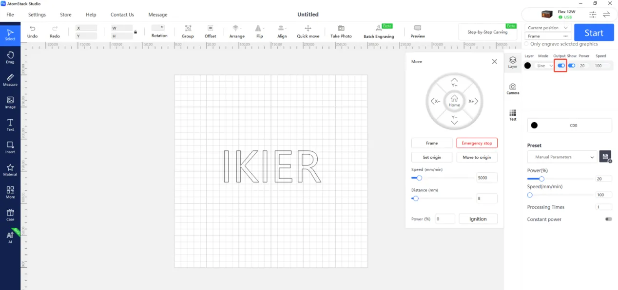
Figure 48
3) Confirm That the S-Value Max Has Not Been Changed (LightBurn Only)
The S-Value Max must remain at 1000 (as shown in Figure 49) and must not be changed. Otherwise, it may affect laser output and service life.
Figure 49
4) Check the Focusing Distance(IR Laser Module)
After placing the material, adjust the laser focusing distance. Swing the fixed-focus rod on the side of the laser module, loosen the laser module fixing screws, and lower the laser module until the tip of the rod touches the material surface, as shown in Figure 50. Then retighten the fixing screws and fold the rod back.
The IR laser is highly sensitive to the focusing distance. Since IR light is invisible, engraving sparks may not be visible if the focusing distance is incorrect.
Figure 50
5) Check the Laser Module Cable
Check that the laser module cable is securely connected. Disconnect and reconnect it if necessary.
6) Check the Mainboard Cable Connection
Open the top cover of the machine and check whether the laser module cable connected to the mainboard is loose, as shown in Figure 51. Disconnect and reconnect it if necessary.
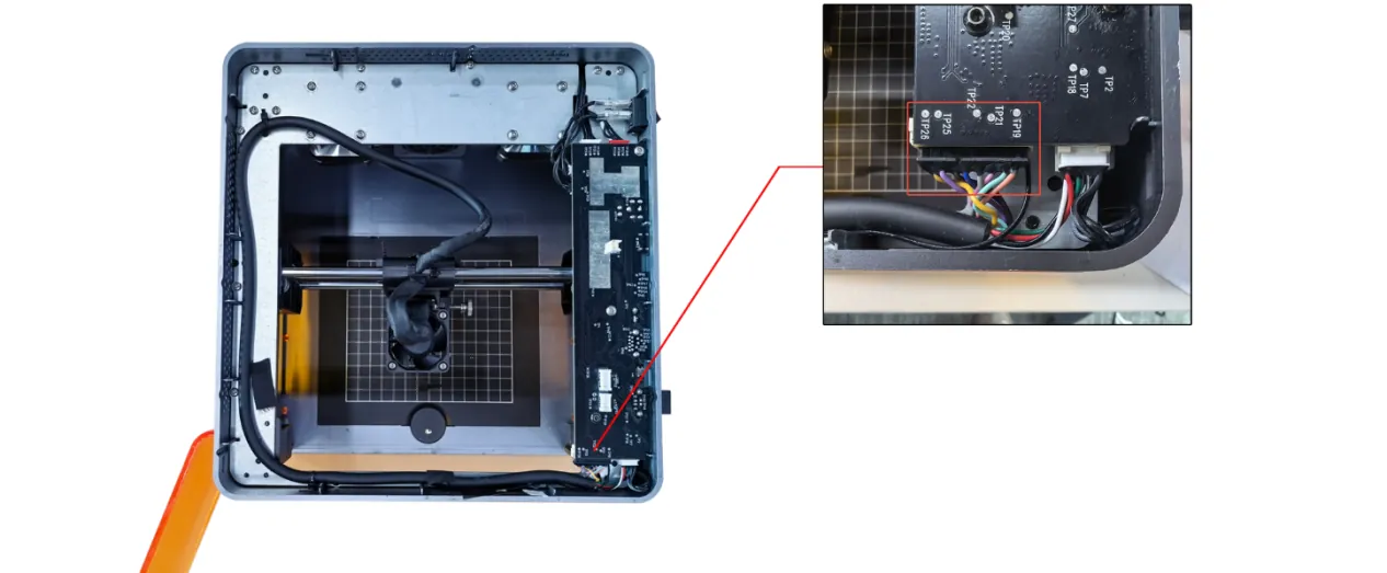
Figure 51
7) Measure the Voltage at the Laser Module Cable
- Disconnect the laser module cable. Run a cutting program at 100% power and a speed of 1 mm/min. Set the multimeter to DC voltage mode and check whether the voltage is 24V between pins 1 and 2 and 5V between pins 2 and 3, as shown in Figure 52.
- Refer to the Flex Pro voltage measurement video for guidance.
Figure 52
8) Contact Customer Support
If you encounter a problem during troubleshooting that you cannot resolve yourself, or if you are unable to determine the cause of the fault, please provide the following information to Customer Support:
- A video showing the issue.
- A description of the troubleshooting steps performed. If voltage measurements were taken, include the measurement results.
- A photo of the laser module's laser-engraved code, as shown in Figure 53.
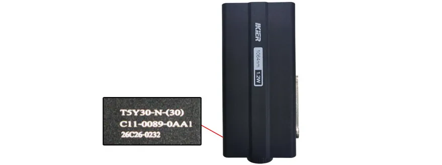
Figure 53
9) Component Replacement Reference
- If the mainboard needs to be replaced, refer to the Flex Pro mainboard replacement video.
- If the laser module needs to be replaced, refer to the Flex Pro laser module replacement video.
- If the mainboard connecting cable needs to be replaced, refer to the Flex Pro mainboard connecting cable replacement video.
¶ Poor Engraving Results
What you see: Poor Engraving Results
Please follow the steps below to troubleshoot the issue.
1) Check the focusing distance
After placing the material, adjust the laser focusing distance. Swing the fixed-focus rod on the side of the laser module, loosen the laser module fixing screws, and lower the laser module until the tip of the rod touches the material surface, as shown in Figure 54. Then retighten the fixing screws and fold the rod back.
The IR laser is highly sensitive to the focusing distance. Since IR light is invisible, engraving sparks may not be visible if the focusing distance is incorrect.
Figure 54
2) Check the Software Parameters
Different materials require different processing parameters. Refer to the parameter table to verify that the power, speed, and speed units are set correctly.
How to access the parameter table:
- Scan the QR code on the machine.
- Check the included USB drive.
- Contact Customer Support.
- AtomStack Studio includes preset processing parameters for some materials.
3) Check the S-Value Max Setting in LightBurn
Figure 55
The S-Value Max setting must remain at 1000, as shown in Figure 55. Do not change this value, as doing so may affect laser power and service life.
4) Check the Protective Window
A dirty or damaged protective window can significantly reduce laser output power. Refer to the “Dirty or Damaged Laser Module Protective Window” section for instructions.
5) Check the Power Supply Output
Insufficient voltage or current directly affects laser output power.
① Measure the Power Adapter Output
Set the multimeter to DC voltage mode and check whether the adapter outputs 24V. If an ammeter is available, measure whether the adapter can provide an output current of up to 3A.
② Measure the Voltage at the Laser Module Cable
Disconnect the laser module cable. Run a cutting program at 100% power and a speed of 1 mm/min. Set the multimeter to DC voltage mode and check whether the voltage is 24V between pins 1 and 2 and 5V between pins 2 and 3, as shown in Figure 56. Refer to the Flex Pro voltage measurement video for guidance.
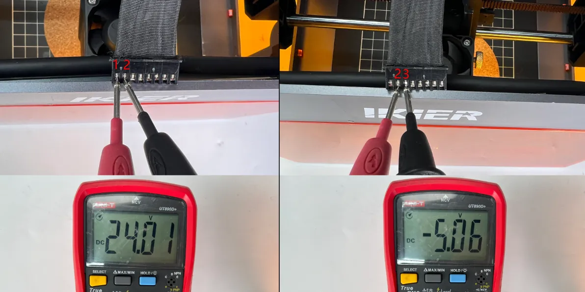
Figure 56
6) Test the Laser Output Power
Secure a sheet of A4 paper and cut it using the recommended settings below to determine whether the laser output power is abnormal.
Recommended settings for cutting A4 paper:
- Flex Pro 12W: 60% power, 2000 mm/min speed.
- Flex Pro 7W: 100% power, 1300 mm/min speed.
7) Contact Customer Support
If the above steps do not resolve the issue, please contact Customer Support and provide the following information:
- An engraving video: Clearly show the focusing process, power and speed settings, engraving process, and final result.
- A description of the troubleshooting steps performed: If voltage measurements were taken, include the measurement results.
- An A4 paper cutting video: Clearly show the focusing process, power and speed settings, cutting process, and final result.
- A photo of the laser module's laser-engraved code, as shown in Figure 57.
Figure 57
8) Component Replacement Reference
- If the laser module needs to be replaced, refer to the Flex Pro laser module replacement video.
¶ Distorted Output
What you see: Distorted Engraving Output
Refer to the Flex Pro image distortion troubleshooting video and follow the steps below to identify and resolve the issue.
We recommend engraving a circle or square first, then comparing the actual movement trajectory with the following scenarios to troubleshoot the issue.
1) The Machine Moves Diagonally at a 45° Angle
- Check the motor cables
Disconnect and reconnect the motor cables, then check whether normal operation is restored.
- Check the motor cable connections on the mainboard
Open the top cover of the machine and locate the motor cable connectors on the mainboard near the power switch, as shown in Figure 69. Check whether the connectors are fully seated. If any connector is loose, disconnect and reconnect it, ensuring that it fits securely into the socket.
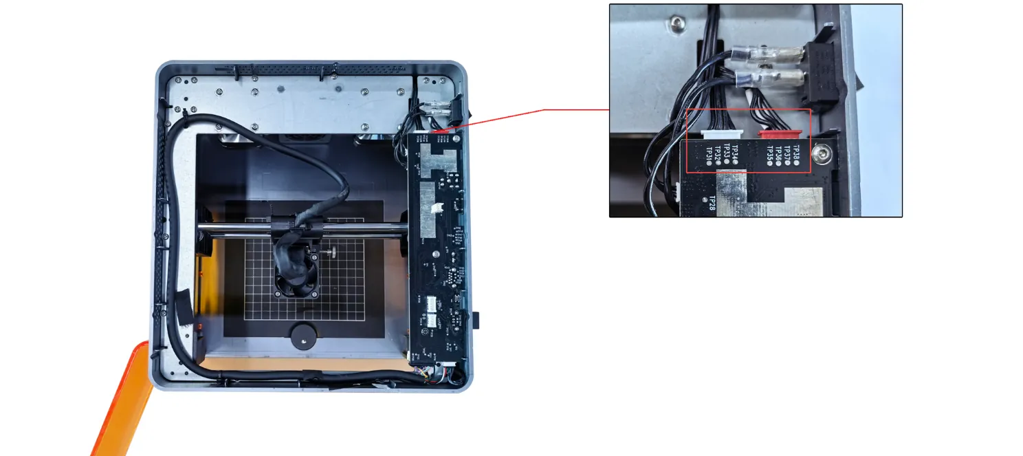
Figure 69
- Check the mechanical drive components
Check whether the motor pulley screws are loose, as shown in Figure 70, and whether the timing belts are too loose.
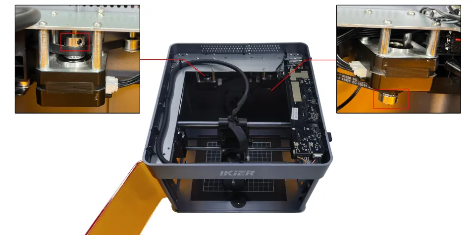
Figure 70
Note
If tightening the pulley screws and adjusting the timing belts do not resolve the issue, proceed directly to Step (2), “Jittering and Diagonal Movement,” for further troubleshooting.
2) Jittering and Diagonal Movement
- The machine moves only toward the upper-left or lower-right corner: This indicates abnormal movement of the left motor.
Disconnect both motor cables and connect the left motor cable (the longer cable) to the right motor. Use the controls to test whether the machine can move toward the upper-left or lower-right corner normally without jittering.
- If the movement is normal, the left motor is faulty.
- If the movement is still abnormal, the motor cable or mainboard motor driver may be faulty.
- The machine moves only toward the upper-right or lower-left corner: This indicates abnormal movement of the right motor.
Disconnect both motor cables and connect the left motor cable (the longer cable) to the right motor. Use the controls to test whether the machine can move toward the upper-right or lower-left corner normally without jittering.
- If the movement is normal, the motor cable or mainboard motor driver may be faulty.
- If the movement is still abnormal, the motor may be faulty.
3) Check the Material
For lightweight materials such as paper or thin wood boards, secure all four corners with magnets. Otherwise, airflow from the machine's exhaust fan or laser module fan may move the material, causing the engraved image to shift or become distorted.
4) Check the Firmware
Incorrect firmware may cause this issue. Send the firmware version to Customer Support for verification.
① Check on the Touchscreen
On the touchscreen, tap “Settings” → “System Update/Reset” to view the mainboard firmware version and touchscreen firmware version, as shown in Figure 71.
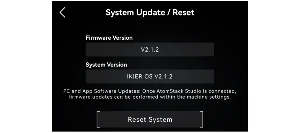
Figure 71
② Check in AtomStack Studio
Click the three-line menu icon in the top-right corner of the software interface to open the device information page. The current firmware version is displayed at the bottom of the page, as shown in Figure 72.
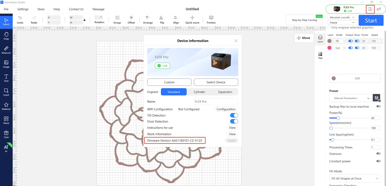
Figure 72
③ Check in the Mobile App
Tap “Settings” below the model name to open the device settings page. The current firmware version is displayed at the bottom of the page, as shown in Figure 73.
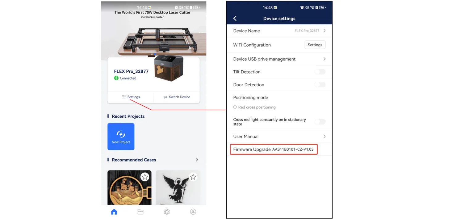
Figure 73
5) Check the Mechanical Structure
If the engraved circle or square is irregular, the issue may be related to the machine's mechanical structure. Check the following components in order.
- Check the timing pulleys: Check whether the pulley screws are loose or the pulleys have shifted out of position, as shown in Figure 74. Adjust them if necessary.
- Check the timing belts: Press the belts by hand to check whether they are too loose. If necessary, adjust them by following the Flex Pro timing belt replacement video.
- Check the guide rollers: Check that all rollers along the timing belt paths operate normally. Ensure there is no debris from timing belt friction inside the machine enclosure.
- Check the linear shafts: Ensure that the surfaces of all three linear shafts are free of friction marks and adequately lubricated.
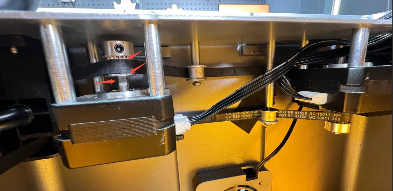
Figure 74
6) Restore Factory Settings
If none of the above steps resolves the issue, refer to the Flex Pro factory reset video and follow the instructions below.
① AtomStack Studio
- Click the Settings menu in the navigation bar and locate “Version:
V*.*.*” in the Settings window. - Click the version number at least seven times in succession. The “Serial Port Log” option (Developer Mode) will appear in the menu bar.
- Click “Serial Port Log” to open the interface. A series of execution commands will appear in the code box.
- Click “Reset” in the bottom-right corner of the interface. If the console indicates that the reset is complete and displays “OK” as the final message, the reset has been completed successfully.
- Click “close” in the top-right corner of the interface to exit.
② LightBurn
Select “Console,” enter $RST=* in the command input box, and click Send, as shown in Figure 75.
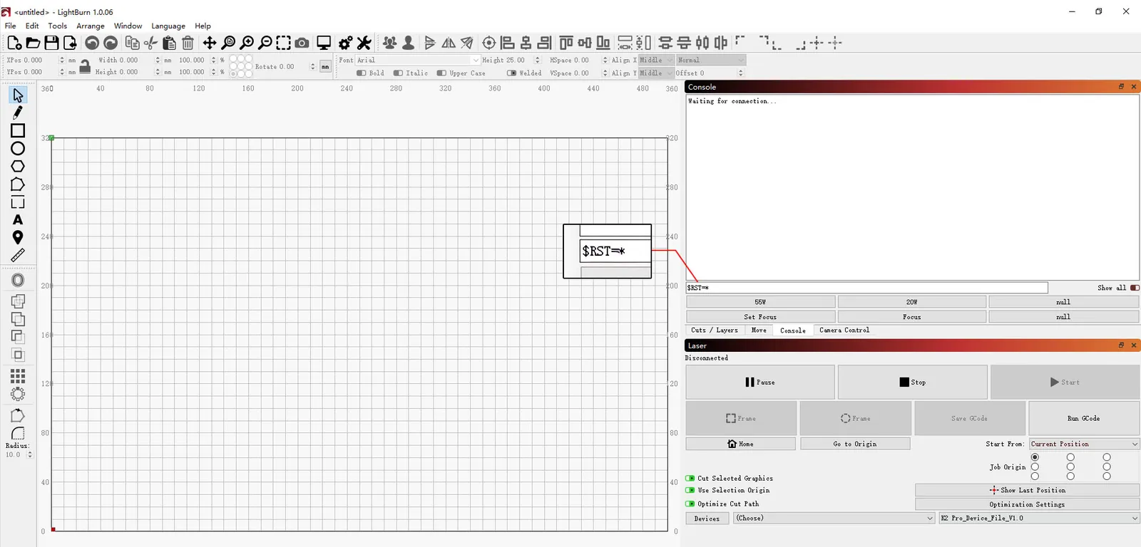
Figure 75
7) Contact Customer Support
If the above steps do not resolve the issue, please contact Customer Support and provide the following information:
- An engraving video: Clearly show the focusing process, power and speed settings, engraving process, and final result.
- A description of the troubleshooting steps performed.
- A screenshot of the firmware version.
- A photo of the device's Serial Number, as shown in Figure 76.
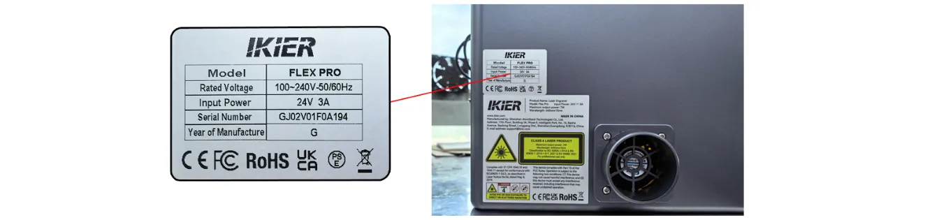
Figure 76
8) Component Replacement Reference
- If a motor needs to be replaced, refer to the Flex Pro motor replacement video.
- For linear shaft maintenance, refer to the Flex Pro enclosure maintenance video.
- If the mainboard needs to be replaced, refer to the Flex Pro mainboard replacement video.
- If a motor connecting cable needs to be replaced, refer to the Flex Pro motor connecting cable replacement video.
¶ Mirrored Output
What you see: The Engraved Output Is Mirrored
Please follow the steps below to troubleshoot the issue one by one:
1) Check the Software and Firmware Versions
Check whether the software and engraver firmware are up to date. If an update is available, update them before testing again.
2) Check the Mainboard Motor Cable Connections
Open the top cover of the enclosure and check whether the motor cable connectors on the mainboard are correctly positioned (the red connector should be near the power switch, as shown in Figure 77). If a connector is plugged in the wrong direction, reconnect it in the correct orientation.
Figure 77
3) Restore Factory Settings
If the above steps do not resolve the issue, refer to the Flex Pro factory reset video and follow the steps below:
① AtomStack Studio
- Click Settings in the navigation bar and locate “Version:
V*.*.*” in the Settings window. - Click the version number seven or more times consecutively. “Serial Port Log” (Developer Mode) will appear in the menu bar.
- Click “Serial Port Log” to open the interface. A series of execution codes will appear in the code box.
- Click “Reset” in the bottom-right corner. If the code box indicates that the reset is complete and ends with “OK”, the reset has been completed successfully.
- Click “Close” in the top-right corner to exit the interface.
② LightBurn
Select the “Console” window, enter $RST=* in the code box, and click Send, as shown in Figure 78.
Figure 78
¶ Skewed at 45°
What you see: Engraved Output Is Skewed at a 45° Angle
Please follow the steps below to troubleshoot the issue:
1) Check the Timing Pulley Screws and Timing Belts
- Check whether the motor timing pulley screws (Figure 79) are loose. If any screws are loose, tighten them first.
Figure 79
- Check whether the timing belts are too loose. If so, adjust the belt tension.
2) Check the Motor Cables
- Check for damage: Carefully inspect the motor cables for any signs of damage.
- Reconnect the cables: Disconnect the motor cables and reconnect them, then check whether normal operation is restored.
3) Check the Motor Cable Connections on the Mainboard
Open the top cover of the enclosure and locate the motor cable connectors on the mainboard near the power switch (Figure 80). Check that the connectors are fully inserted. If any connector is loose, disconnect it and reconnect it, ensuring that it fits securely into the socket.
Figure 80
4) Check the Motors
Refer to the Flex Pro motor cable swap troubleshooting video and follow the instructions below.
- If the machine moves only toward the upper-left or lower-right corner, the left motor may be malfunctioning.
Disconnect both motor cables and connect the left motor cable (the longer cable) to the right motor. Use the controls to check whether the machine can move toward the upper-left or lower-right corner normally without jittering. If it moves normally, the left motor is faulty. If the issue persists, the motor connecting cable or the mainboard motor driver may be faulty.
- If the machine moves only toward the upper-right or lower-left corner, the right motor may be malfunctioning.
Disconnect both motor cables and connect the left motor cable (the longer cable) to the right motor. Use the controls to check whether the machine can move toward the upper-right or lower-left corner normally without jittering. If it moves normally, the motor connecting cable or the mainboard motor driver may be faulty. If the issue persists, the motor may be faulty.
5) Contact Customer Support
If the above steps do not resolve the issue, please contact Customer Support and provide the following information:
- Troubleshooting video: Clearly show the software operation steps and the direction in which the laser module moves.
- Troubleshooting steps performed: Describe the steps you have already taken.
- Device Serial Number: Provide a photo of the device Serial Number (Figure 81).
Figure 81
6) Component Replacement References
- To replace the motor, refer to the Flex Pro motor replacement video.
- To replace the mainboard, refer to the Flex Pro mainboard replacement video.
- To replace the motor connecting cable, refer to the Flex Pro motor connecting cable replacement video.