Flex Pro Motion: Homing, Limits, 45° Move
← All Flex Pro troubleshooting
Homing fails, the head moves only diagonally, engraving stops, area or limit-switch alarms appear, or the machine hits the frame during engraving.
Disconnect power before disassembly or electrical testing. Turn off the engraving machine before removing the laser and disconnecting its cable, or removing and reinserting the TF card. Do not turn off the machine or remove the TF card during a firmware update.
¶ Homing Failure
What you see: Homing Failure
Please follow the steps below to troubleshoot the issue one by one.
Homing Logic:
The laser module moves to the far left along the X-axis until the limit switch is triggered, then automatically rebounds to the X-axis 0 coordinate. It then moves to the front along the Y-axis until the limit switch is triggered, then rebounds to the Y-axis 0 coordinate. Homing is complete when both axes return to their zero coordinates.
1) Check Whether the Laser Module Moves Normally
① Moves diagonally at a 45° angle every time
- Check the motor cable connections
Unplug the motor cables and reconnect them to see whether the issue is resolved.
- Check the motor cable connections on the mainboard
Open the top cover of the machine and locate the motor cable connector on the mainboard near the power switch, as shown in Figure 22. Check whether it is fully plugged in. If it is loose, unplug it and reconnect it, ensuring that the connector fits securely into the socket.
- Check the mechanical transmission components
Check whether the screws on the motor pulleys (as shown in Figure 23) are loose and whether the timing belts are too loose.
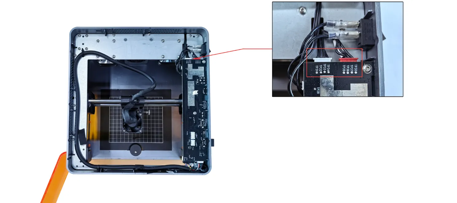
Figure 22
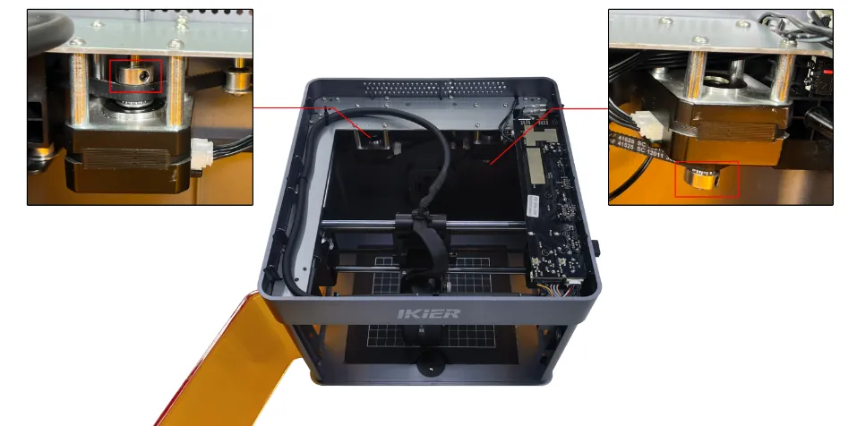
Figure 23
② Moves in the opposite direction
- Restore the factory settings by following the Flex Pro factory reset video.
- If only the Y-axis moves in the opposite direction, check whether the motor cable is connected to the wrong port on the mainboard. The correct port is the one with the red connector near the power switch, as shown in Figure 24.
Figure 24
③ Moves diagonally and makes unusual noises
- Moves only toward the upper-left or lower-right corner: The left motor is malfunctioning.
Unplug both motor cables and connect the left motor cable (the longer cable) to the right motor. Use the controls to move the laser module and check whether it can move toward the upper-left or lower-right corner normally without shaking.
- If it moves normally, the left motor is faulty.
- If it still does not move normally, the motor cable or mainboard driver may be faulty.
- Moves only toward the upper-right or lower-left corner: The right motor is malfunctioning.
Unplug both motor cables and connect the left motor cable (the longer cable) to the right motor. Use the controls to move the laser module and check whether it can move toward the upper-right or lower-left corner normally without shaking.
- If it moves normally, the motor cable or mainboard driver may be faulty.
- If it still does not move normally, the motor may be faulty.
④ Nothing happens when you click Home
If the engraver does not respond and the laser module does not move after you click Home, turn off the engraver and close the software, then restart both to see whether the issue is resolved. If the issue persists, refer to the "Unable to Power On Normally" section for troubleshooting.
2) Check Whether the Limit Switches Work Properly
Manually press the left and right limit switches beside the laser module, as well as the front and rear Y-axis limit switches on the right side, as shown in Figure 25. Check whether they trigger the alarm sound (beeping).
① The switches trigger normally
The limit switches are working properly. Proceed directly to Step (3).
② The switches do not trigger
- Check the limit switch cables
Check whether the limit switch cables are loose or broken.
- Check the cable connections on the mainboard
Open the top cover of the engraver and check whether the limit switch cables are loose at the mainboard, as shown in Figure 26.
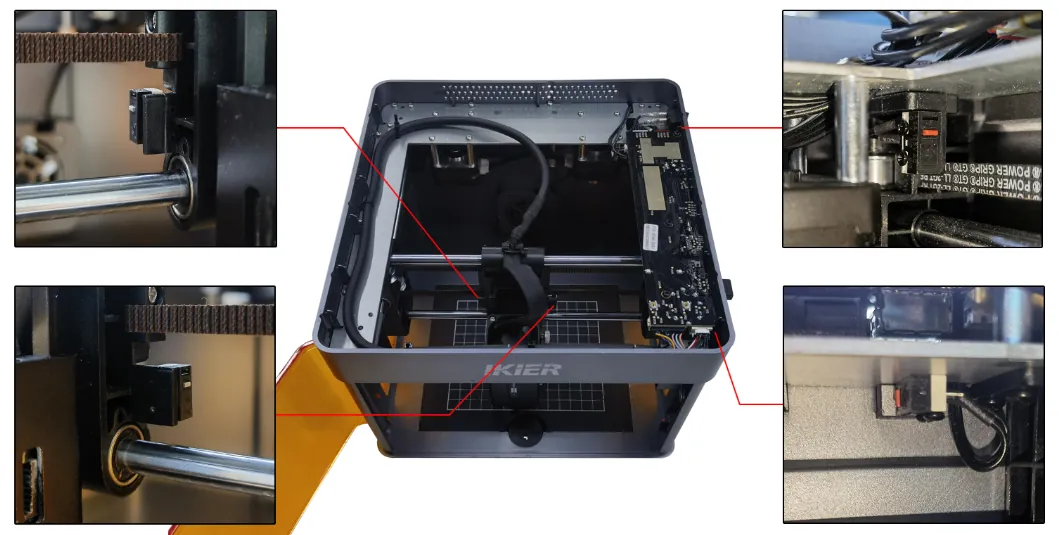
Figure 25
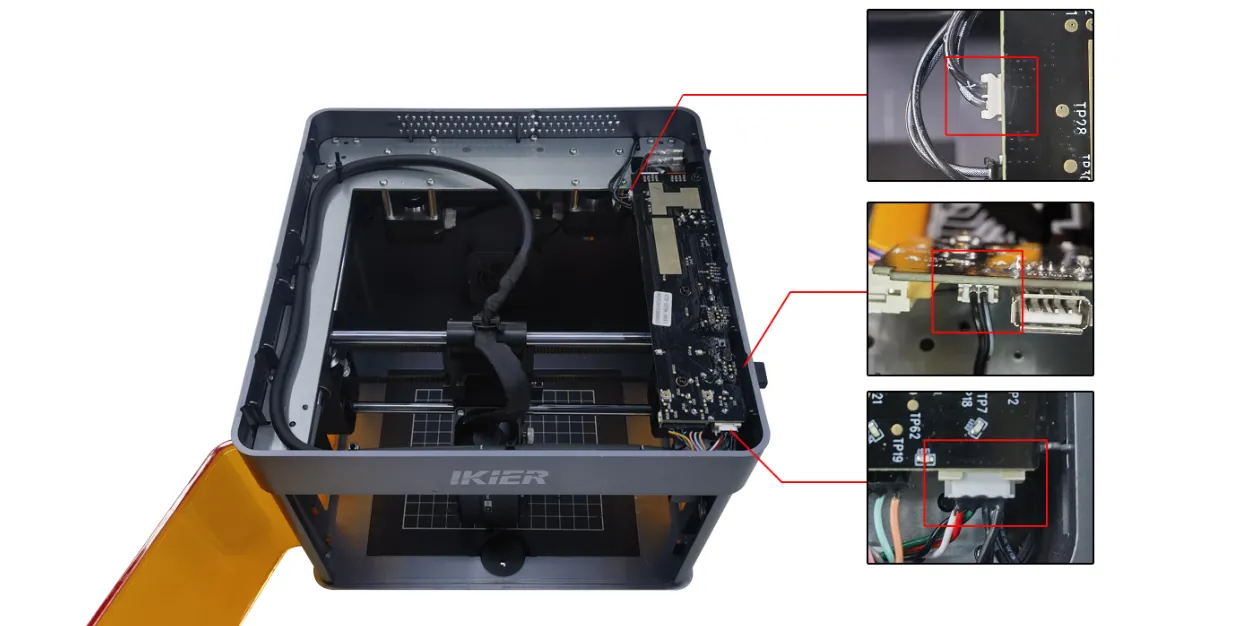
Figure 26
3) Check the Mainboard Firmware
Incorrect firmware may cause this issue. Send the firmware version information to Customer Support for confirmation.
① Check on the touchscreen
On the touchscreen, tap Settings → System Update/Reset. The mainboard firmware version and touchscreen firmware version are displayed on this page, as shown in Figure 27.
② Check in AtomStack Studio
Click the three-line menu icon in the upper-right corner of the software interface to open the device information page. The current firmware version is displayed at the bottom of the page, as shown in Figure 28.
③ Check in the mobile app
Tap Settings below the model name to open the device settings page. The current firmware version is displayed at the bottom of the page, as shown in Figure 29.
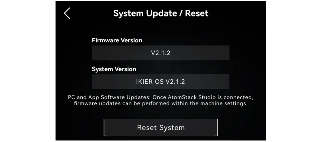
Figure 27
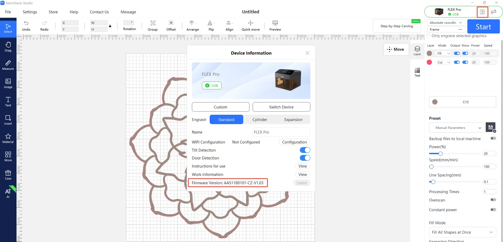
Figure 28
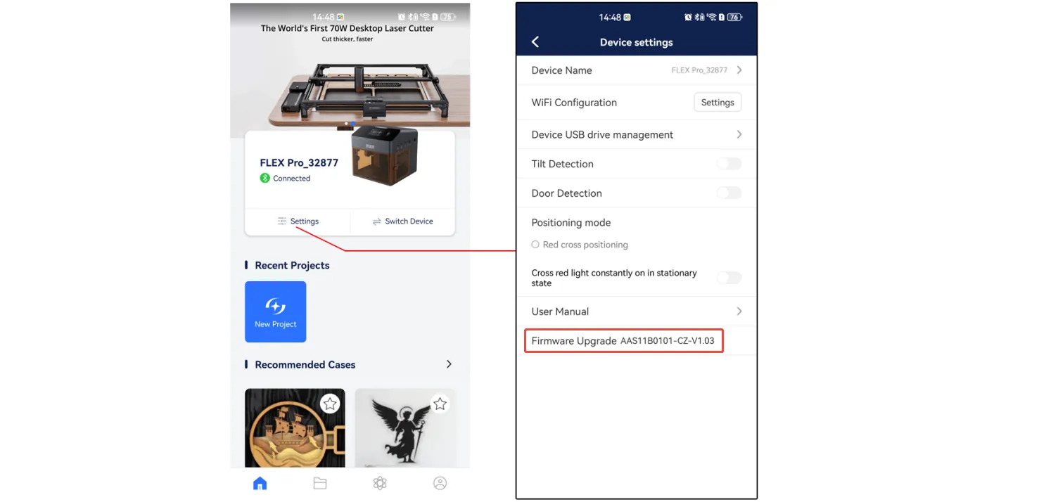
Figure 29
4) Restore Factory Settings
If none of the above steps resolves the issue, follow the Flex Pro factory reset video and perform the steps below.
① AtomStack Studio
- Click Settings in the navigation bar and locate Version:
V*.*.*in the settings window. - Click the version number at least seven times consecutively. The Serial Port Log option (Developer Mode) will appear in the menu.
- Click Serial Port Log to open the interface. A series of execution commands will appear in the code window.
- Click Reset in the lower-right corner. If the console reports that the reset is complete and the final output is OK, the reset has been completed successfully.
- Click Close in the upper-right corner to exit the interface.
② LightBurn
Open the Console window, enter $RST=* in the command field, and click Send, as shown in Figure 30.
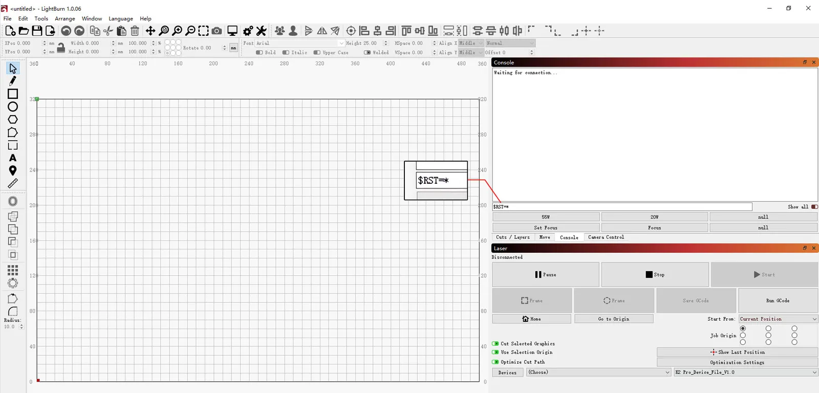
Figure 30
5) Contact Customer Support
If none of the above steps resolves the issue, contact Customer Support and provide the following information:
- Video of the issue: The video must show the entire homing process and the test in which the limit switches are pressed manually.
- Troubleshooting steps performed: Provide a description of the steps you have already tried.
- Serial Number photo: Provide a photo of the Serial Number label on the back of the machine, as shown in Figure 31.
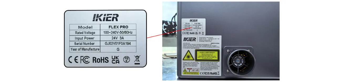
Figure 31
6) Replacement Part References
- If the mainboard needs to be replaced, refer to the Flex Pro mainboard replacement video.
- If a limit switch needs to be replaced, refer to the Flex Pro X-axis/Y-axis limit switch replacement video.
¶ Diagonal-Only Motion
What you see: The Laser Module Can Only Move Diagonally at a 45° Angle and Cannot Move Normally Up, Down, Left, or Right
Please follow the steps below to troubleshoot the issue:
1) Check the Timing Pulley Screws and Timing Belts
- Check whether the motor timing pulley screws (Figure 82) are loose. If any screws are loose, tighten them first.
Figure 82
- Check whether the timing belts are too loose. If so, adjust the belt tension.
2) Check the Motor Cables
Disconnect the motor cables and reconnect them, then check whether normal operation is restored.
3) Check the Motor Cable Connections on the Mainboard
Open the top cover of the enclosure and locate the motor cable connectors on the mainboard near the power switch (Figure 83). Check that the connectors are fully inserted. If any connector is loose, disconnect it and reconnect it, ensuring that it fits securely into the socket.
Figure 83
4) Check the Motors
Refer to the Flex Pro motor cable swap troubleshooting video and follow the instructions below.
- If the machine moves only toward the upper-left or lower-right corner, the left motor may be malfunctioning.
Disconnect both motor cables and connect the left motor cable (the longer cable) to the right motor. Use the controls to check whether the machine can move toward the upper-left or lower-right corner normally without jittering. If it moves normally, the left motor is faulty. If the issue persists, the motor connecting cable or the mainboard motor driver may be faulty.
- If the machine moves only toward the upper-right or lower-left corner, the right motor may be malfunctioning.
Disconnect both motor cables and connect the left motor cable (the longer cable) to the right motor. Use the controls to check whether the machine can move toward the upper-right or lower-left corner normally without jittering. If it moves normally, the motor connecting cable or the mainboard motor driver may be faulty. If the issue persists, the motor may be faulty.
5) Contact Customer Support
If the above steps do not resolve the issue, please contact Customer Support and provide the following information:
- Troubleshooting video: Clearly show the software operation steps and the direction in which the laser module moves.
- Troubleshooting steps performed: Describe the steps you have already taken.
- Device Serial Number: Provide a photo of the device Serial Number (Figure 84).
Figure 84
6) Component Replacement References
- To replace the motor, refer to the Flex Pro motor replacement video.
- To replace the mainboard, refer to the Flex Pro mainboard replacement video.
- To replace the motor connecting cable, refer to the Flex Pro motor connecting cable replacement video.
¶ Engraving Stops
What you see: Engraving Stops Unexpectedly
Please follow the steps below to troubleshoot the issue one by one:
1) Check for Software Error Messages
When this issue occurs, check whether the software displays any error messages, then troubleshoot accordingly.
① Check the USB Key (Software Error: USB Key Not Connected)
Check whether the USB Key is inserted, as shown in Figure 85. If it is already inserted, gently move the USB Key and check whether its indicator light turns green.
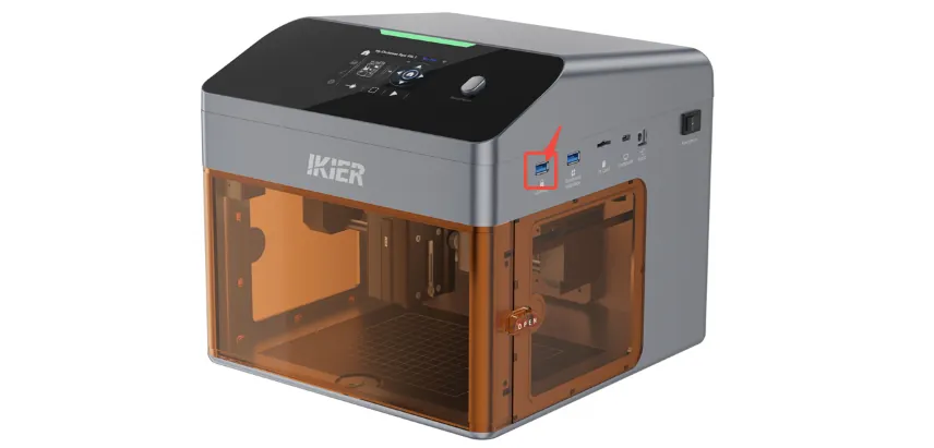
Figure 85
② Check Whether the Top Cover Is Fully Closed
The mainboard is equipped with a cover detection switch (Figure 86). If the top cover is not fully closed, the device will enter an alarm state and cannot operate normally. The software will display “Top Cover Open”.
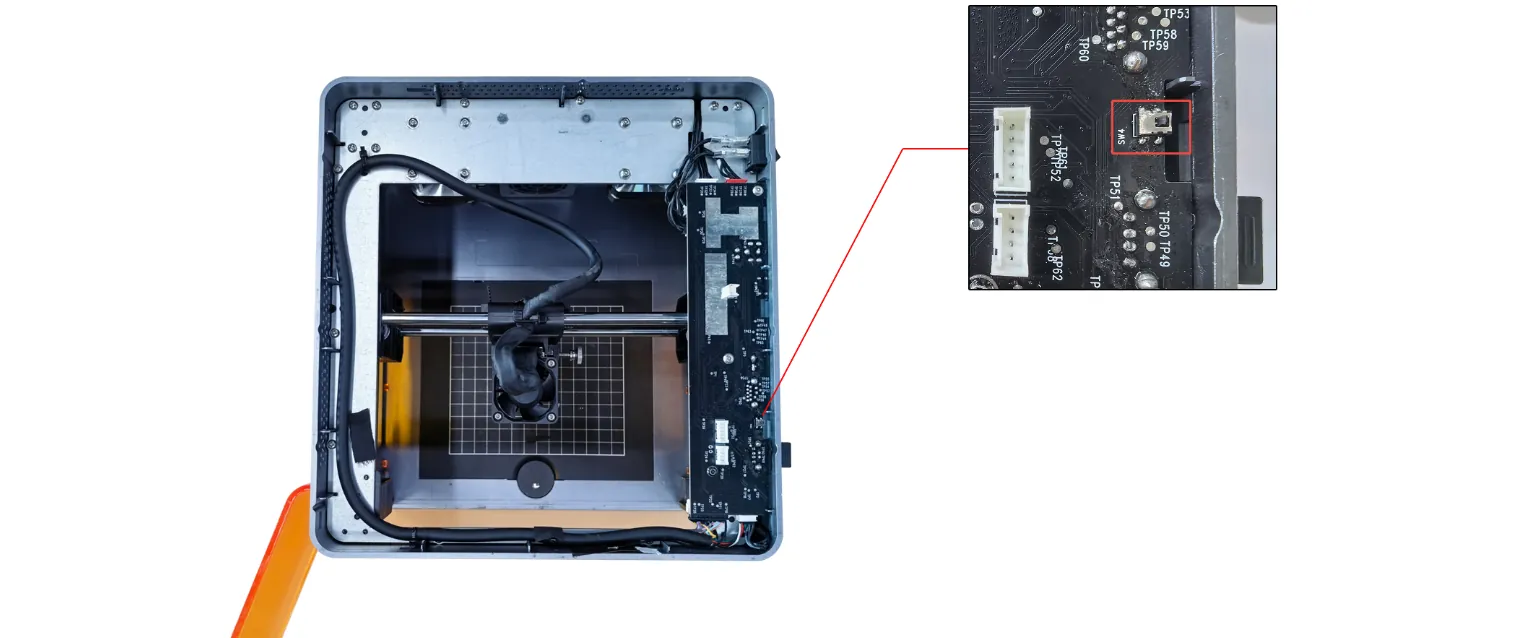
Figure 86
③ Check the Enclosure Door (Software Error: Enclosure Open)
Check whether the enclosure door is fully closed and close it again if necessary. If the issue persists, press the two trigger points on the enclosure door by hand (Figure 87) and check whether the status indicator turns green.
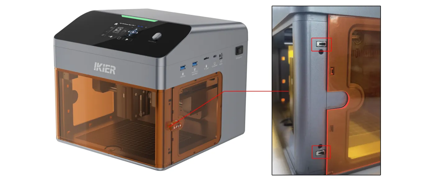
Figure 87
- If the indicator turns green after pressing: The enclosure door was not fully closed. Check for any obstructions preventing it from closing properly.
- If the alarm persists after pressing: Check whether the cables connecting the door detection limit switch to the mainboard are loose. Disconnect and reconnect them.
④ Check the Laser Module Position
Manually move the laser module to the center of the enclosure and check whether the indicator light turns green.
⑤ Restore Factory Settings
If the above steps do not resolve the issue, refer to the Flex Pro factory reset video and follow the steps below:
- AtomStack Studio
- Click Settings in the navigation bar and locate “Version:
V*.*.*” in the Settings window. - Click the version number seven or more times consecutively. “Serial Port Log” (Developer Mode) will appear in the menu bar.
- Click “Serial Port Log” to open the interface. A series of execution codes will appear in the code box.
- Click “Reset” in the bottom-right corner. If the code box indicates that the reset is complete and ends with “OK”, the reset has been completed successfully.
- Click “Close” in the top-right corner to exit the interface.
- Click Settings in the navigation bar and locate “Version:
- LightBurn
Select the “Console” window, enter $RST=* in the code box, and click Send, as shown in Figure 88.
Figure 88
2) Check the Type-C Data Cable Connection
- Make sure the Type-C data cable is securely connected. Disconnect and reconnect it, or try a different USB port on the computer.
- Make sure the Type-C data cable is not disturbed during engraving, as contact with the cable may interrupt communication.
3) Check the Computer Operating System
If you are using Windows 11, do not minimize the software or switch it to the background during engraving, as the system may restrict background communication and cause the process to stop.
4) Try Different Control Software
We recommend using AtomStack Studio or LightBurn. Try engraving with the other software and check whether the issue occurs again to rule out software version problems.
5) Try a Different Power Adapter
Try engraving with another DC 24V power adapter and check whether the issue occurs again to rule out unstable power supply from the adapter.
6) Contact Customer Support
If the above steps do not resolve the issue, please contact Customer Support and provide the following information:
- Troubleshooting video: If the issue is easy to reproduce, record the entire operation. If it takes a long time to occur, record the issue when the machine stops, along with any software error messages.
- Troubleshooting steps performed: Describe the steps you have already taken.
- Device Serial Number: Provide a photo of the Serial Number on the back of the enclosure (Figure 89).
Figure 89
7) Component Replacement Reference
- To replace the mainboard, refer to the Flex Pro mainboard replacement video.
¶ Area Exceeded
What you see: Software Reports That the Engraving Area Is Exceeded
Please follow the steps below to troubleshoot the issue one by one:
1) Check the Engraving File Size
Check whether the current engraving file is entirely within the engraving area. Ensure that there are no other graphics or accidentally selected extra elements outside the engraving area.
2) Check the Selected Coordinate Mode
- Absolute Coordinates: This alarm is generally not triggered as long as the file is within the engraving area.
- Current Position: You must manually move the laser module or use the software to move it to a suitable position. Ensure that there is sufficient clearance around the edges of the engraving path; otherwise, the alarm may be triggered.
When using Current Position mode, we recommend using the Frame function before engraving to confirm that the engraving area meets the requirements.
3) Check the Software Error Message
- X-axis error: Check whether the laser module has reached the left or right limit switch (at the edge of the engraving area).
- Y-axis error: Check whether the laser module has reached the front or rear Y-axis limit switch on the right side (at the edge of the engraving area).
4) Manually Trigger the Limit Switches
Press the left and right limit switches beside the laser module and the front and rear Y-axis limit switches on the right side by hand, as shown in Figure 90. Check whether the alarm sound (beeping) is triggered normally.
- If a switch does not trigger the alarm, check whether the limit switch is damaged or its cable is loose.
- If the cable is connected properly but the switch still does not trigger the alarm, the limit switch itself may be damaged.
Figure 90
5) Check the Mainboard Cable Connections
Open the top cover of the enclosure and check the limit switch cables on the mainboard for loose connections, breaks, or poor contact, as shown in Figure 91.
Figure 91
6) Restore Factory Settings
If the above steps do not resolve the issue, refer to the Flex Pro factory reset video and follow the steps below:
① AtomStack Studio
- Click Settings in the navigation bar and locate “Version:
V*.*.*” in the Settings window. - Click the version number seven or more times consecutively. “Serial Port Log” (Developer Mode) will appear in the menu bar.
- Click “Serial Port Log” to open the interface. A series of execution codes will appear in the code box.
- Click “Reset” in the bottom-right corner. If the code box indicates that the reset is complete and ends with “OK”, the reset has been completed successfully.
- Click “Close” in the top-right corner to exit the interface.
② LightBurn
Select the “Console” window, enter $RST=* in the code box, and click Send, as shown in Figure 92.
Figure 92
7) Contact Customer Support
If the above steps do not resolve the issue, please contact Customer Support and provide the following information:
- Troubleshooting video: If the issue is easy to reproduce, record the entire operation. If it takes a long time to occur, record the issue when the alarm is triggered, along with the information displayed in the software code box.
- Troubleshooting steps performed: Describe the steps you have already taken.
- Photos of the fault: If you identify a faulty component or connection during troubleshooting, provide clear photos.
- Device Serial Number: Provide a photo of the Serial Number on the back of the enclosure (Figure 93).
Figure 93
8) Component Replacement References
- To replace the mainboard, refer to the Flex Pro mainboard replacement video.
- To replace the limit switches, refer to the Flex Pro X-axis/Y-axis limit switch replacement video.
¶ Area Alarm at Center
What you see: The Laser Module Triggers an Alarm Even in the Center of the Engraving Area, Reporting That the Engraving Area Is Exceeded
Please follow the steps below to troubleshoot the issue one by one:
1) Manually Trigger the Limit Switches
Press the left and right limit switches beside the laser module and the front and rear Y-axis limit switches on the right side by hand, as shown in Figure 94. Check whether the alarm sound (beeping) is triggered normally.
- If a switch does not trigger the alarm, check whether the limit switch is damaged or its cable is loose.
- If the cable is connected properly but the switch still does not trigger the alarm, the limit switch itself may be damaged.
Figure 94
2) Check the Mainboard Cable Connections
Open the top cover of the enclosure and check the limit switch cables on the mainboard for loose connections, breaks, or poor contact, as shown in Figure 95.
Figure 95
3) Restore Factory Settings
If the above steps do not resolve the issue, refer to the Flex Pro factory reset video and follow the steps below:
① AtomStack Studio
- Click Settings in the navigation bar and locate “Version:
V*.*.*” in the Settings window. - Click the version number seven or more times consecutively. “Serial Port Log” (Developer Mode) will appear in the menu bar.
- Click “Serial Port Log” to open the interface. A series of execution codes will appear in the code box.
- Click “Reset” in the bottom-right corner. If the code box indicates that the reset is complete and ends with “OK”, the reset has been completed successfully.
- Click “Close” in the top-right corner to exit the interface.
② LightBurn
Select the “Console” window, enter $RST=* in the code box, and click Send, as shown in Figure 96.
Figure 96
4) Contact Customer Support
If the above steps do not resolve the issue, please contact Customer Support and provide the following information:
- Troubleshooting video: Record the issue when the alarm is triggered, along with the information displayed in the software code box.
- Troubleshooting steps performed: Describe the steps you have already taken.
- Photos of the fault: If you identify a faulty component or connection during troubleshooting, provide clear photos.
- Device Serial Number: Provide a photo of the Serial Number on the back of the enclosure (Figure 97).
Figure 97
5) Component Replacement References
- To replace the mainboard, refer to the Flex Pro mainboard replacement video.
- To replace the limit switches, refer to the Flex Pro X-axis/Y-axis limit switch replacement video.
¶ Limit Switch Not Found
What you see: Software Reports “Limit Switch Not Detected”
Please follow the steps below to troubleshoot the issue one by one:
1) Check Whether the Mainboard Firmware Is Correct
Incorrect firmware may cause this issue. Send the firmware version to Customer Support for verification.
① Check on the Touchscreen
On the touchscreen, tap “Settings” → “System Update/Reset” to view the mainboard firmware version and touchscreen firmware version, as shown in Figure 98.
Figure 98
② Check in AtomStack Studio
Click the three-line menu icon in the upper-right corner of the software interface to open the device information page. The current firmware version is displayed at the bottom of the page, as shown in Figure 99.
Figure 99
③ Check in the Mobile App
Tap “Settings” below the model name to open the device settings page. The current firmware version is displayed at the bottom of the page, as shown in Figure 100.
Figure 100
2) Manually Trigger the Limit Switches
Press the left and right limit switches beside the laser module and the front and rear Y-axis limit switches on the right side by hand, as shown in Figure 101. Check whether the alarm sound (beeping) is triggered normally.
Figure 101
- If a switch does not trigger the alarm, check whether the limit switch is damaged or its cable is loose.
- If the cable is connected properly but the switch still does not trigger the alarm, the limit switch itself may be damaged.
3) Check the Mainboard Cable Connections
Open the top cover of the enclosure and check the limit switch cables on the mainboard for loose connections, breaks, or poor contact, as shown in Figure 102.
Figure 102
4) Restore Factory Settings
If the above steps do not resolve the issue, refer to the Flex Pro factory reset video and follow the steps below:
① AtomStack Studio
- Click Settings in the navigation bar and locate “Version:
V*.*.*” in the Settings window. - Click the version number seven or more times consecutively. “Serial Port Log” (Developer Mode) will appear in the menu bar.
- Click “Serial Port Log” to open the interface. A series of execution codes will appear in the code box.
- Click “Reset” in the bottom-right corner. If the code box indicates that the reset is complete and ends with “OK”, the reset has been completed successfully.
- Click “Close” in the top-right corner to exit the interface.
② LightBurn
Select the “Console” window, enter $RST=* in the code box, and click Send, as shown in Figure 103.
Figure 103
5) Contact Customer Support
If the above steps do not resolve the issue, please contact Customer Support and provide the following information:
- Troubleshooting video: Record the issue when the alarm is triggered, the information displayed in the software code box, and the procedure for manually triggering the limit switches.
- Troubleshooting steps performed: Describe the steps you have already taken.
- Photos of the fault: If you identify a faulty component or connection during troubleshooting, provide clear photos.
- Device Serial Number: Provide a photo of the Serial Number on the back of the enclosure (Figure 104).
Figure 104
6) Component Replacement References
- To replace the mainboard, refer to the Flex Pro mainboard replacement video.
- To replace the limit switches, refer to the Flex Pro X-axis/Y-axis limit switch replacement video.
¶ Hits Frame When Engraving
What you see: The Laser Module Moves Normally During Framing but Hits the Frame During Engraving
Please follow the steps below to troubleshoot the issue one by one:
1) Confirm the Laser Type
- Blue Diode Laser: Skip directly to Step (2).
- IR Laser: Because there is an offset between the laser emission point and the center of the red crosshair, the laser module travels a little farther during engraving than during framing.
Note
When installing the IR laser module, you must manually set the engraving area in LightBurn to 105 mm × 100 mm.
2) Test with Different Control Software
We recommend using AtomStack Studio or LightBurn. Try engraving with the other software and check whether the issue occurs again to rule out software version compatibility issues.
3) Restore Factory Settings
If the above steps do not resolve the issue, refer to the Flex Pro factory reset video and follow the steps below:
① AtomStack Studio
- Click Settings in the navigation bar and locate “Version:
V*.*.*” in the Settings window. - Click the version number seven or more times consecutively. “Serial Port Log” (Developer Mode) will appear in the menu bar.
- Click “Serial Port Log” to open the interface. A series of execution codes will appear in the code box.
- Click “Reset” in the bottom-right corner. If the code box indicates that the reset is complete and ends with “OK”, the reset has been completed successfully.
- Click “Close” in the top-right corner to exit the interface.
② LightBurn
Select the “Console” window, enter $RST=* in the code box, and click Send, as shown in Figure 113.
Figure 113
4) Contact Customer Support
If the above steps do not resolve the issue, please contact Customer Support and provide the following information:
- Troubleshooting video: Show the software interface, file layout, framing process, and the laser module hitting the frame.
- Troubleshooting steps performed: Describe the steps you have already taken.
- Device Serial Number: Provide a photo of the Serial Number on the back of the enclosure (Figure 114).
Figure 114