¶ Flex Troubleshooting
Choose the section that matches the symptom and complete each check in order. Disconnect power before disassembly or electrical testing.
¶ 1. Quick Troubleshooting Guide
| Problem | Priority Checks |
|---|---|
| Unable to power on | Check whether the power adapter and power switch are functioning properly; check whether the status indicator and mainboard power indicators are normal. |
| Computer connection failed | Confirm that the machine is powered on and the connection is properly established; confirm that the USB driver is installed; check the baud rate in the LightBurn software. |
| "No U Disk Detected" message | Check whether the TF card is inserted; confirm that the TF card capacity is ≤ 16 GB; confirm that the TF card can be read normally by the computer and is formatted in FAT32. |
| Status indicator stays red | Check the software alarm message and perform the corresponding troubleshooting steps; try restoring the machine to normal operation. |
| "USB Key Not Inserted" alarm | Check whether the USB Key is properly inserted and making good contact; confirm that the machine's top cover is properly closed. |
| Laser power is reduced | Check the protective window and focusing lens; check the engraving parameters and S-value Max in LightBurn; check the power adapter. |
| Laser does not emit light | Check the focus; check the laser cable connection; measure the voltage of the laser cable. |
| Distorted engraving output | Check the synchronization belt; check the motor; check the linear shafts. |
| Poor engraving results | Check the software parameters; check the protective window and focusing lens; check the S-value Max; check the power adapter. |
| Abnormal alarm | Troubleshoot according to the alarm message. If the alarm is caused by the limit switch, manually press the limit switch to confirm whether it is triggered properly, then check the laser cable. |
| Red Crosshair and Laser Offset | Recalibrate the red crosshair and working laser. |
| Runs only at a 45° angle | Check the motor cable; check whether the motor synchronization screws are loose; check the motor cable on the mainboard. |
¶ 2. Unable to Power On Normally
Follow the steps below in sequence:
- Check the Status Indicator on the Top
① The indicator is solid red (alarm status)
- Check the USB Key (software alarm: USB safety lock not detected)
Check whether the USB Key is properly inserted, as shown in Figure 10. Alternatively, gently wiggle the USB Key and check whether the indicator turns green.
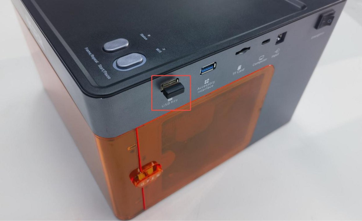
Figure 10
- Check the Enclosure Door (software alarm: enclosure is abnormally open)
Check whether the enclosure door is fully closed. You can open and close the door again. If the issue persists, press the two trigger points on the enclosure door by hand and check whether the status indicator returns to normal green. → If the indicator returns to normal green after pressing: The enclosure door was not fully closed. Check whether any foreign objects are obstructing the door. → If the alarm persists after pressing: Check whether the detection limit switch on the enclosure door and the cable connected to the mainboard are loose. Disconnect and reconnect the cable.
- Check the Laser Position
Manually move the laser to the center of the enclosure and check whether the indicator turns green. (Software alarm: the limit switch is triggered.)
- Try Restoring Factory Settings
Restore the factory settings through the "Serial Port Log" developer mode in AtomStack Studio, or enter “ $RST=* ”in the Console command input box in LightBurn to restore the factory settings, as shown in Figure 11.
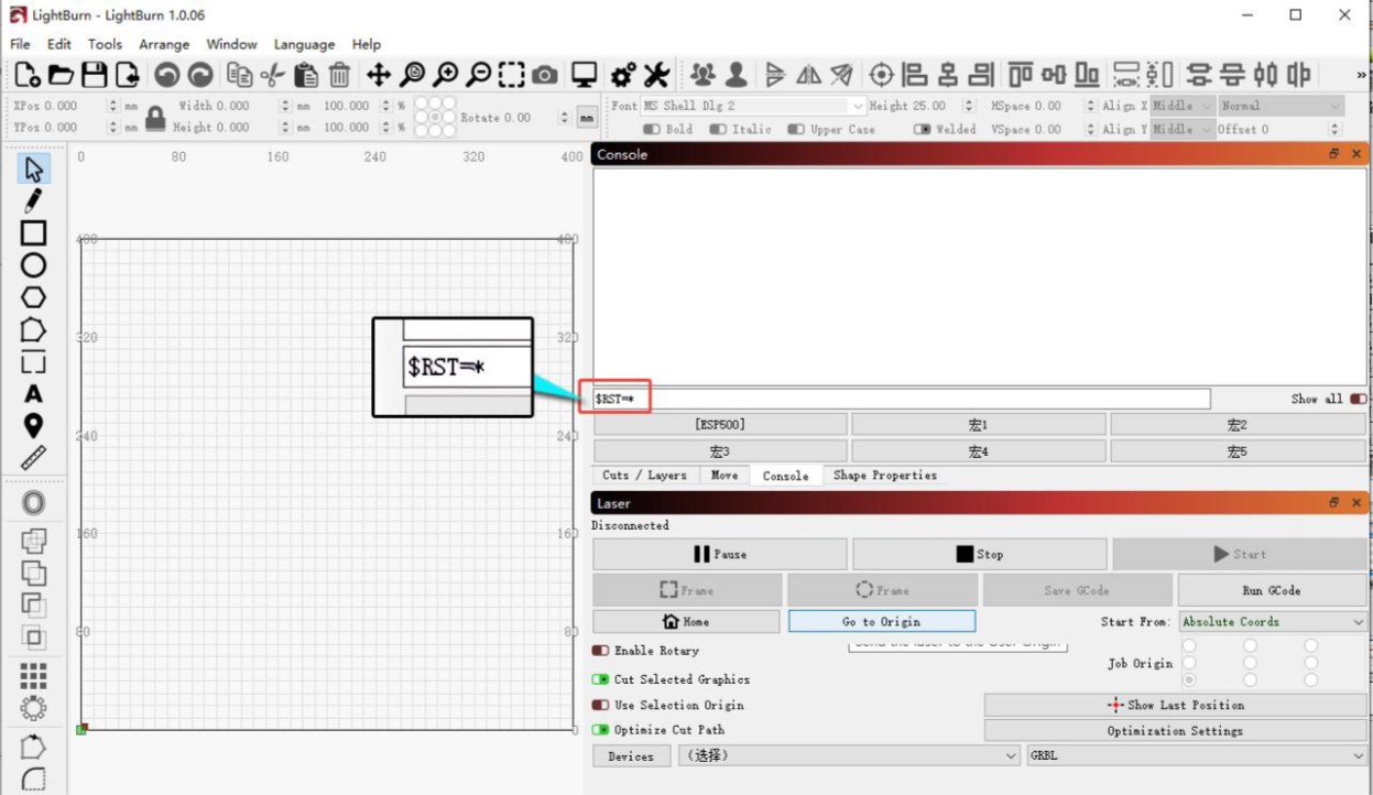
Figure 11
② The Indicator Is Off (Mainboard Not Powered On) Check the mainboard power indicator: Open the enclosure door and check whether the mainboard power indicator at the top right is illuminated green, as shown in Figure 12.
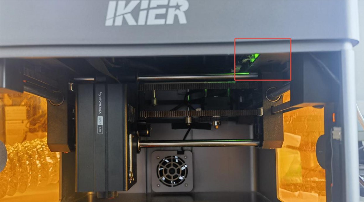
Figure 12
-
Green: The mainboard firmware may be missing. Contact Customer Service to request a firmware re-flash.
-
Off: The power adapter or power switch may be faulty.
→ Power Adapter Troubleshooting: Use a multimeter set to the DC voltage mode to measure the adapter output voltage and check whether it is 24 V. If you do not have a multimeter, you can determine whether the adapter is faulty by connecting the two power switch wires on the mainboard and checking for sparks. If the adapter is confirmed to be faulty, provide Customer Service with a photo of the Serial Number on the back of the enclosure so that a replacement part can be arranged. → Power Switch Troubleshooting: Open the enclosure door and push upward firmly from the inside to open the top cover of the enclosure. At the upper right, disconnect the two wires from the power switch, as shown in Figure 13. Slide the plastic protective sleeve downward, then connect the two metal terminals together, as shown in Figure 14. Connect the power supply and check whether the machine can power on normally. If the machine powers on normally after the terminals are shorted, contact Customer Service and provide the troubleshooting results and a photo of the Serial Number so that a replacement part can be arranged.
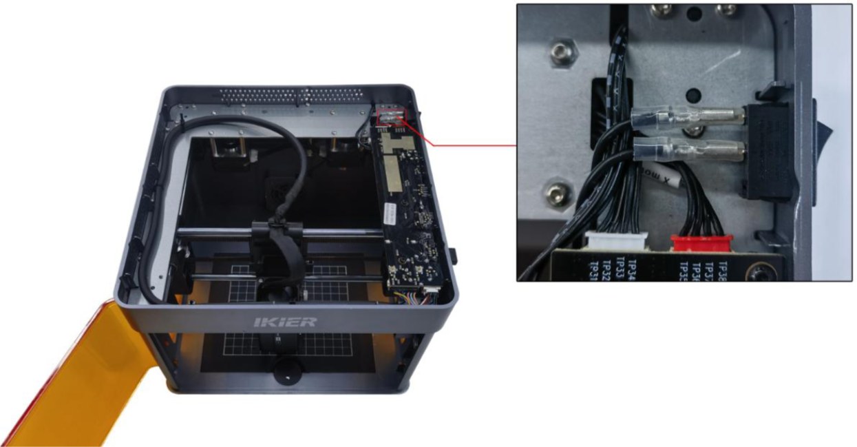
Figure 13
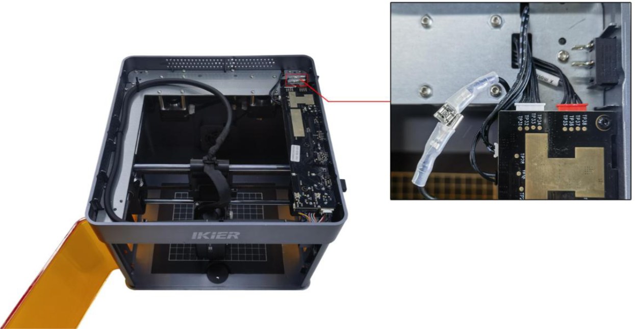
Figure 14
- Contact Customer Service
If none of the above steps resolve the issue, send the following information to Customer Service:
-
A video showing the problem.
-
A description of the troubleshooting steps already performed.
-
A photo of the machine's Serial Number (as shown in Figure 15).
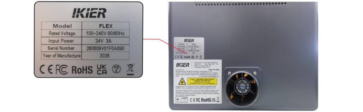
Figure 15
- Replacement Part References
¶ 3. Computer Connection Failed
Follow the steps below to troubleshoot the issue one by one:
- Confirm That the Machine Is Powered On Properly
Check whether the status indicator on the top of the enclosure is illuminated solid green (normal standby status). If the indicator is off or red, first refer to the "Unable to Power On Normally" section for troubleshooting.
- Confirm That the Connection Is Correct
-
When using a Type-C data cable, the Type-C connector must be plugged into the “Computer” port on the laser engraver (see the "Unboxing and Installation" section for details).
-
For Windows, you can plug either the Type-C or Type-A connector of the Type-C data cable into a USB port on the computer. For desktop computers, it is recommended to connect the cable to a USB port on the back of the computer.
-
For macOS, the Type-C connector of the Type-C data cable cannot be connected directly to the computer.
You must use a “hub/docking station”(as shown in Figure 16) to connect the Type-A connector of the Type-C data cable to the computer.
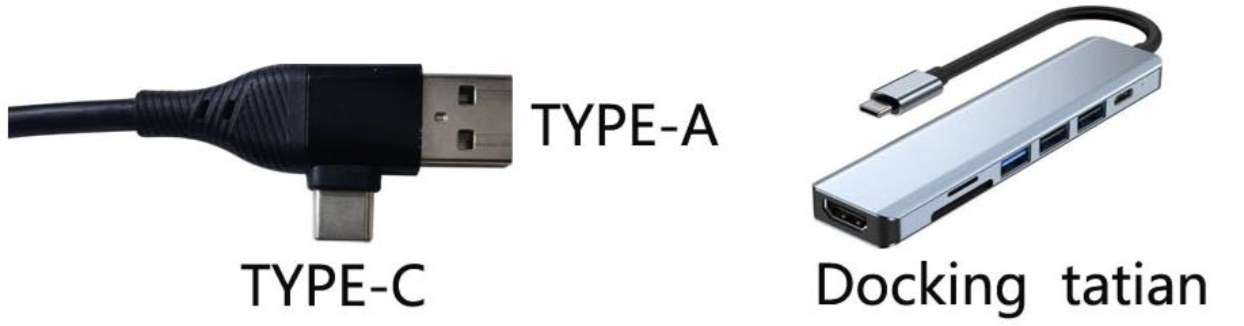
Figure 16
- Note: Be sure to use a Type-C data cable that supports data transmission. Some cables support charging only and cannot establish communication between the computer and the laser engraver.
- Confirm That the Serial Port Driver Is Installed
The serial port driver must be installed before using the device for the first time. Download the driver from the links below:
-
Windows Driver Download: https://asa.atomstack.com/downloadWindowsDrivers.do3
-
macOS Driver Download: https://asa.atomstack.com/downloadMacDrivers.do3
Verify That the Serial Port Is Recognized: On your computer, open “Device Manager” → “Ports (COM & LPT)”and check whether a serial port with the name CH340 is detected, as shown in Figure 17.
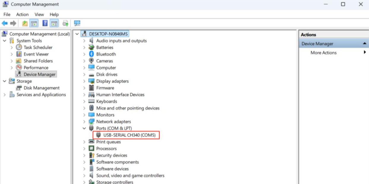
Figure 17
- Confirm That the Software Is Configured Correctly
① AtomStack Studio The software automatically detects the device model, so no additional configuration is required. ② LightBurn Import the Flex configuration file or manually modify the parameters. The parameters that need to be manually configured are as follows:
-
Manually add a GRBL controller.
-
Change the Baud Rate to 460800, as shown in Figure 18.
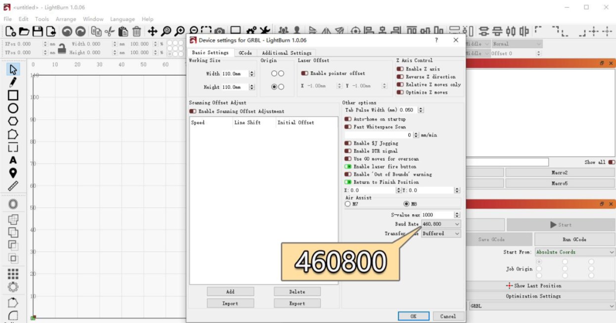
Figure 18
- Set the engraving area as follows:
→Blue Diode Laser: 110 mm × 110 mm →Infrared Laser: 105 mm × 100 mm
- Confirm That the Correct COM Port Is Selected (LightBurn Only)
If multiple COM ports are available on the computer, manually select the COM port corresponding to the engraving machine in LightBurn.
- Try a Different Computer and Type-C Data Cable
-
Try connecting the USB cable to a different USB port on the computer. For desktop computers, it is recommended to use a USB port on the back of the computer case.
-
Replace the Type-C data cable with another cable that supports data transfer. Do not use a cable intended for charging only.
-
If possible, try connecting the machine to another computer to rule out compatibility issues with the USB port or operating system of the current computer.
- Contact Customer Service
If none of the above steps resolve the issue, please provide the following information to Customer Service:
-
Troubleshooting Video: Clearly show how the Type-C data cable is connected (to both the computer and the machine), the connection process, and the serial port (CH340) recognition status in Device Manager.
-
Troubleshooting Steps: Provide a description of the steps that have already been checked or performed.
-
Machine Serial Number: Provide a photo of the machine's Serial Number, as shown in Figure 19.
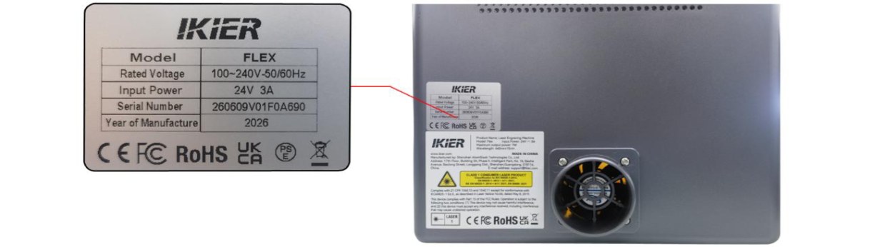
Figure 19
¶ 4. Mobile App Connection Failure
Please follow the steps below to troubleshoot the issue one by one:
- Bluetooth Mode (Recommended)
① Confirm That the App Is Updated to the Latest Version Open the app, tap the icon in the bottom-right corner, and go to "Profile" → "Settings" → "About ATOMSTACK" to check the app version, as shown in Figure 20. If an update is available, complete the update before proceeding.
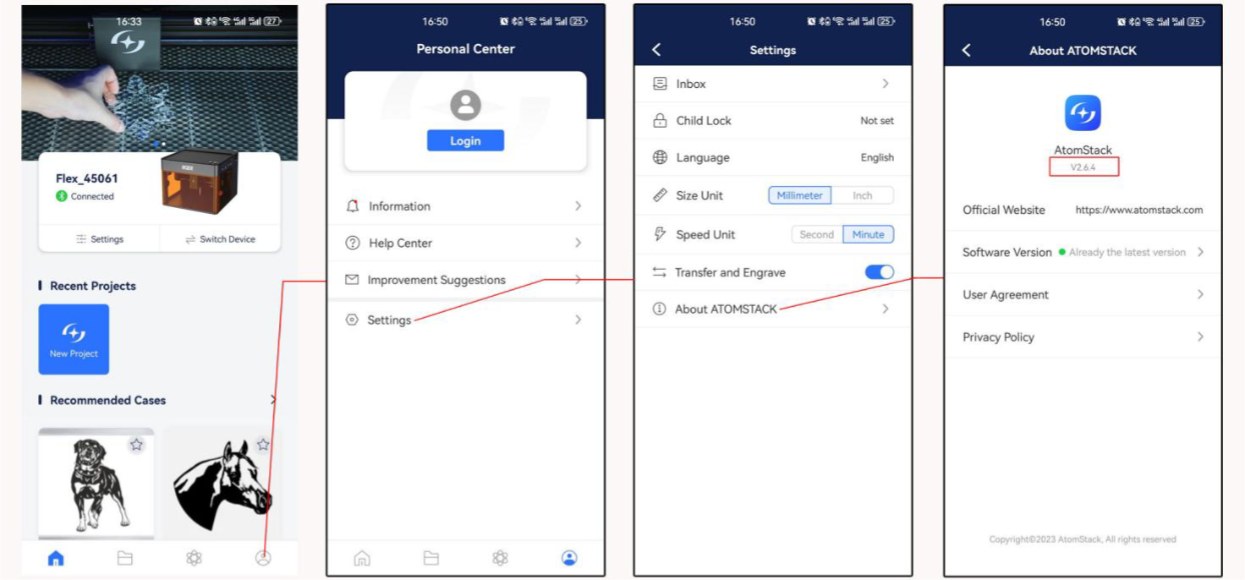
Figure 20
② Confirm That Bluetooth Is Enabled on Your Phone Open your phone's system settings and check whether Bluetooth is enabled. ③ Confirm That the Correct Device Model Is Selected The Flex series includes“Flex”and“Flex Pro”. Check that the correct device model is selected in the app. ④ Restart the Device and App Turn off the engraving machine and completely exit the app. Then restart the machine and the app and try connecting again. ⑤ Try a Different Phone If possible, try connecting the machine using another phone to rule out compatibility issues with the current phone.
- Wi-Fi Mode
① Confirm That Wi-Fi Connection Mode Has Been Enabled Press and hold the“Start/Pause”button and check whether the Wi-Fi indicator is flashing white. ② Confirm That the Wi-Fi Connection Is Not Occupied Make sure that the engraving machine's Wi-Fi connection is not being used by another phone or software. ③ Restart the Device and App Turn off the engraving machine and completely exit the app. Then restart the machine and the app and try connecting again. ④ Try a Different Phone If possible, try connecting the machine using another phone to rule out compatibility issues with the current phone.
- Contact Customer Service
If the connection issue persists after completing all the troubleshooting steps above, please provide the following information to Customer Service:
-
Operation Video: Record a complete video of the connection process, including the operations performed on the phone screen and the status of the device.
-
App Version: In the app, go to "Profile" → "Settings" → "About ATOMSTACK" to check the app version.
-
Engraving Machine Firmware Version: After successfully connecting the machine using the computer software, go to the Device Information page to check the firmware version, as shown in Figure 21.
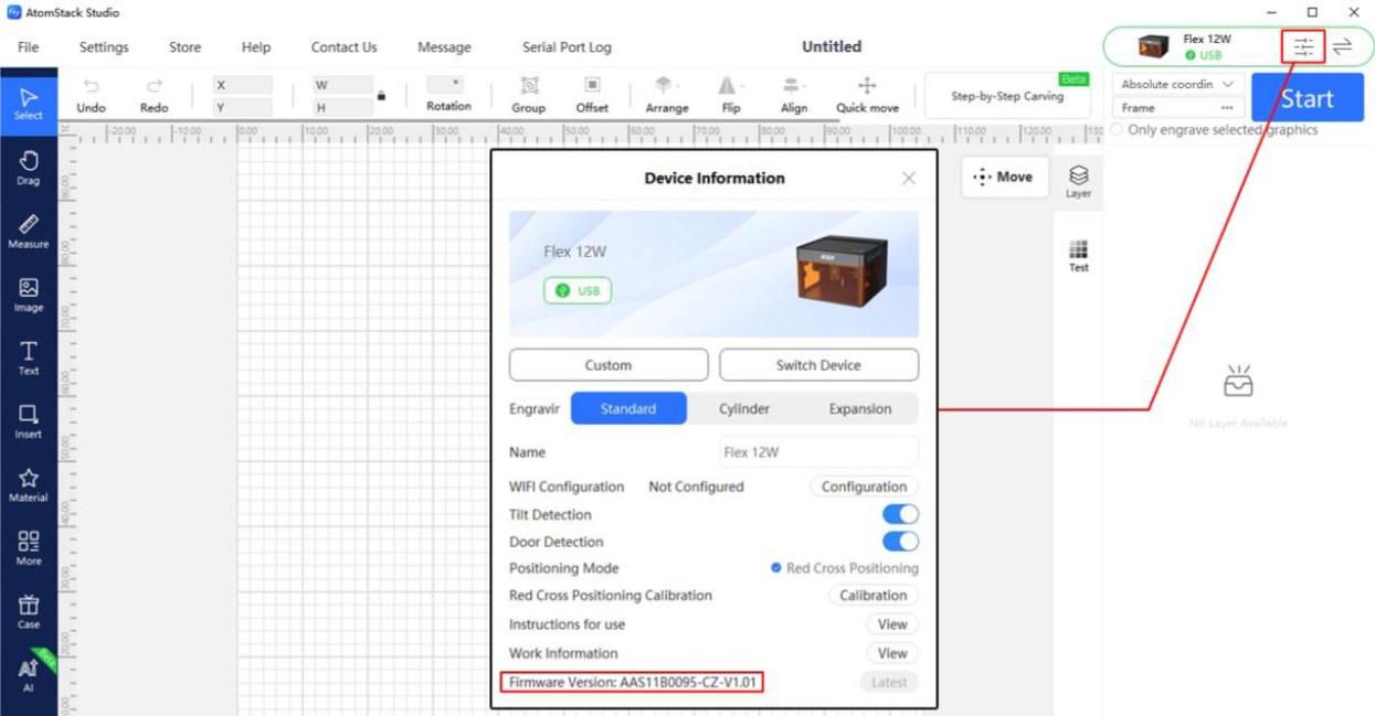
Figure 21
¶ 5. "USB Flash Drive Not Inserted" Message Appears When Engraving via Wi-Fi
Please follow the steps below to troubleshoot the issue one by one:
- Troubleshooting Steps
① Confirm That the TF Card Is Inserted Check whether a TF card is inserted into the TF card slot of the machine, and make sure that the original TF card provided with the machine is being used. ② Confirm That the TF Card Can Be Read and Written Normally Insert the TF card into a card reader and connect it to a computer. Check whether the computer can read from and write to the TF card normally.
-
The TF card can be read and written normally and is the original card provided with the machine → The mainboard may be faulty. Continue with the next troubleshooting step.
-
The TF card cannot be read or written → Format the TF card to FAT32 and then reinsert it into the machine to try again. ③ Try Replacing the TF Card Replace the TF card with another card with a capacity of 16 GB or less for testing. Cards with a capacity of more than 16 GB may not be recognized by the machine. ④ Confirm That the Firmware Has Not Been Upgraded Without Authorization The firmware of some models does not support TF card reading. If the user has upgraded the firmware without authorization, please inform Customer Service of this situation.
- Contact Customer Service
If the connection issue persists after completing all the troubleshooting steps above, please contact Customer Service and provide the following information:
-
Troubleshooting Video: Include the issue and the read/write test performed on the computer.
-
Device Firmware Version: As shown in Figure 22.
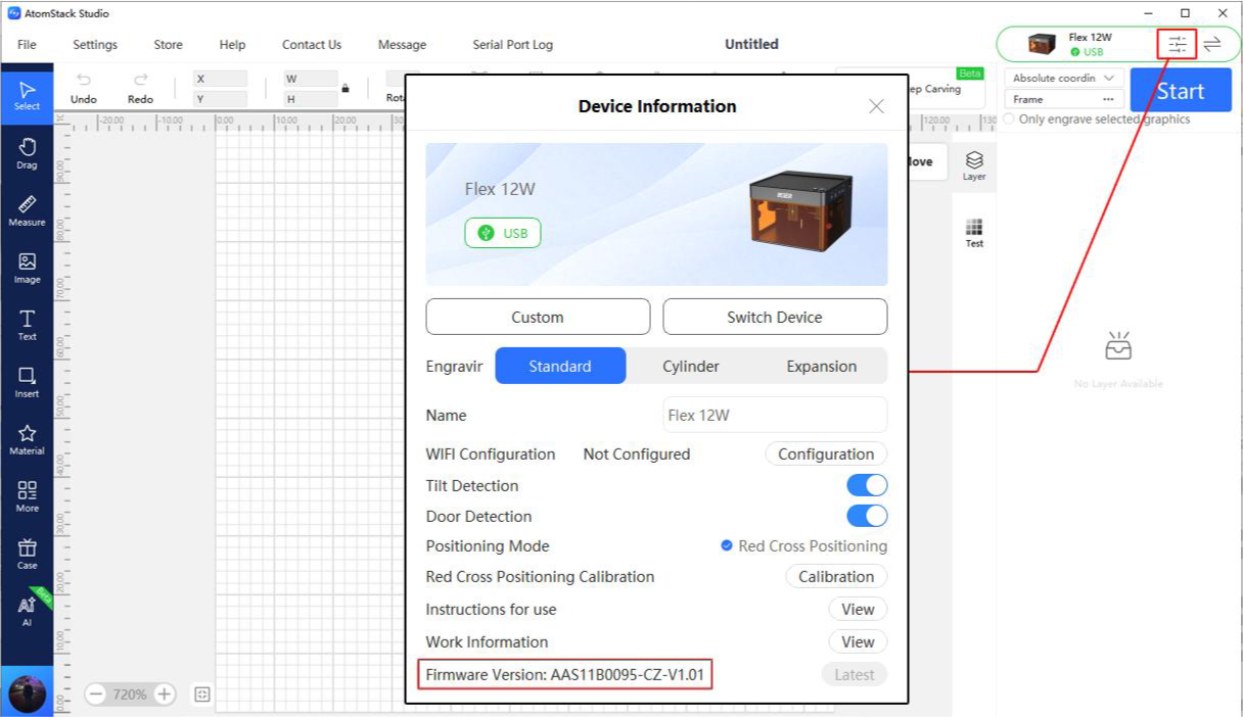
Figure 22
- Serial Number: Provide a photo of the Serial Number, as shown in Figure 23.
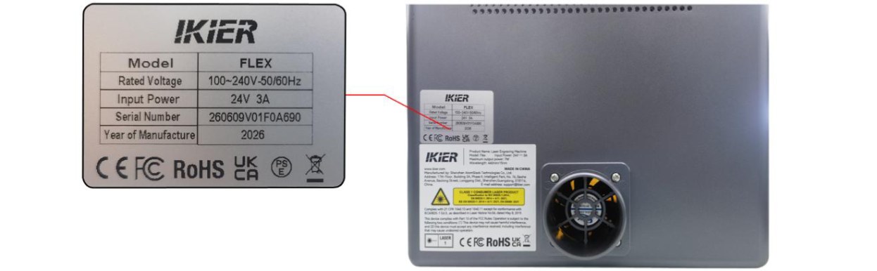
Figure 23
- Troubleshooting Steps: Provide a description of the steps that have already been checked or performed.
¶ 6. The Status Indicator Remains Red After Powering On
Follow the steps below to troubleshoot the issue.
- Note: A red indicator indicates an alarm status.
- Check the Alarm Information
Connect the device using AtomStack Studio. If the device is in an alarm state, the software will display the corresponding alarm message. Troubleshoot the issue according to the alarm message: ① USB Key Not Connected
- Check whether the USB Key is inserted, as shown in Figure 24. Alternatively, gently move the USB Key and check whether the indicator turns green.
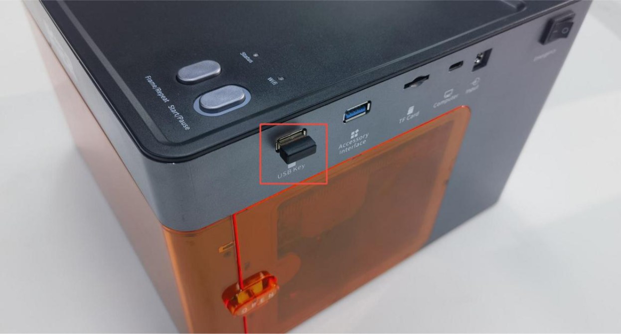
Figure 24
- Check whether the top cover of the enclosure is properly closed (the top cover is equipped with an lid-open detection function). Open and close the top cover again, or press the detection switch by hand (as shown in Figure 25) to check whether the status indicator returns to normal green.
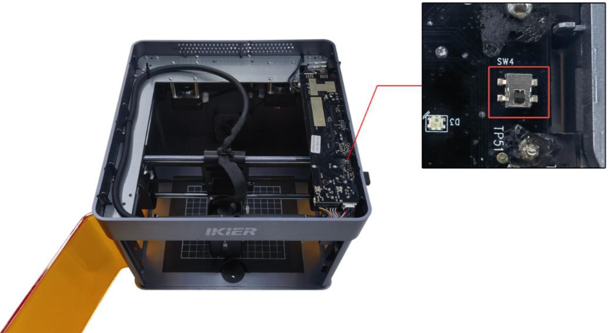
Figure 25
② Abnormal Enclosure Opening
-
Check whether the enclosure door is fully closed. Open and close the door again.
-
Press the two switch trigger points on the enclosure door by hand to check whether the machine returns to normal operation. → Normal after pressing: The enclosure door was not fully closed. Check whether any foreign objects are obstructing the door. → Alarm persists after pressing: Check whether the enclosure door detection limit switch and the connector on the mainboard are loose. Disconnect and reconnect the connector. ③ Limit Switch Triggered by Collision Move the laser head to the center of the enclosure by hand and check whether the indicator turns green. If the machine still indicates that a limit switch has been triggered by a collision, press the X-axis limit switch and Y-axis limit switch by hand in sequence (as shown in Figure 26). Check whether pressing each limit switch triggers the alarm (beeping sound) to determine whether the limit switch is damaged.
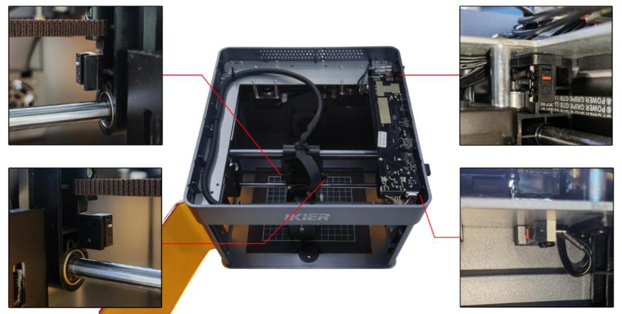
Figure 26
④ Tilt Alarm Make sure that the engraving machine is placed on a level surface. If the alarm persists, open the top cover of the enclosure and tighten the fixing screw next to the buzzer on the mainboard, as shown in Figure 27.
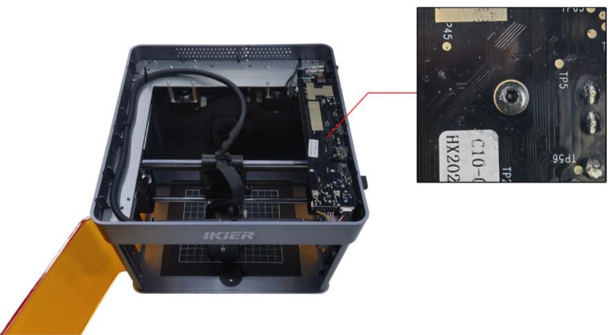
Figure 27
- Restore Factory Settings
If none of the above steps resolve the issue, restore the machine to factory settings, or upgrade the firmware using a TF card to rule out abnormal parameter settings as the cause.
- Contact Customer Service
If you identify a problem during troubleshooting but cannot resolve it yourself, or if the cause of the fault cannot be determined, please provide the following information to Customer Service:
-
Troubleshooting Video: The video must clearly show the issue.
-
Troubleshooting Steps: Provide a description of the steps that have already been checked or performed.
-
Device Serial Number: Provide a photo of the device Serial Number, as shown in Figure 28.
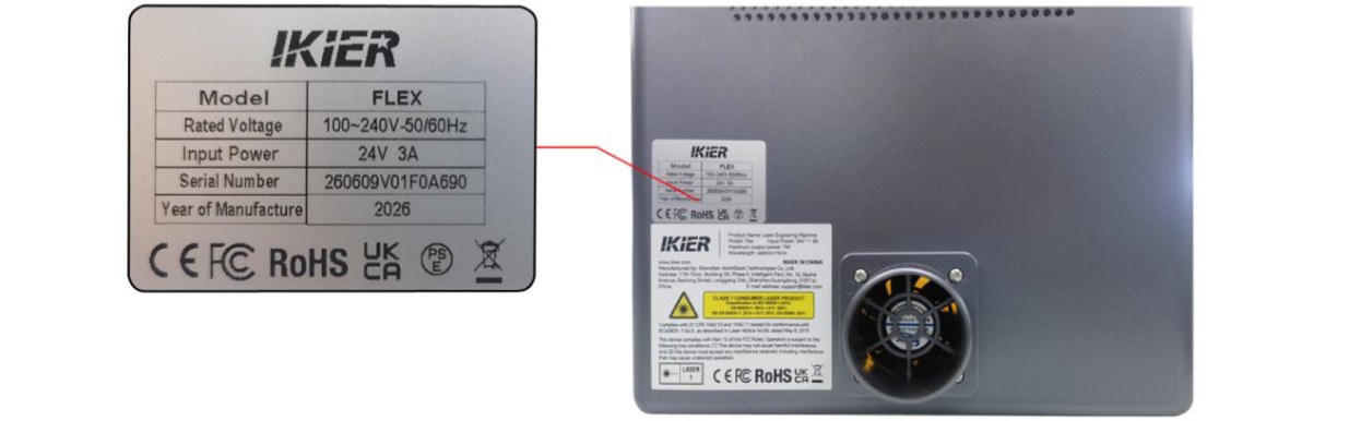
Figure 28
¶ 7. The Engraving Machine Cannot Recognize the TF Card
Please follow the steps below to troubleshoot the issue:
- Reinsert the TF Card
Turn off the engraving machine, remove the TF card, and then reinsert it. Power on the machine and check whether the TF card can be recognized normally.
- Check the Storage Capacity
A TF card with a capacity of 16 GB or less is recommended. A card with a larger capacity may not be recognized by the engraving machine.
- Check the TF Card Read/Write Function
Turn off the engraving machine and remove the TF card. Insert it into a card reader (not included) and connect the card reader to a computer. Check whether the TF card can be recognized normally.
-
The computer recognizes the TF card and can read and write data normally, but the engraving machine still cannot recognize it: Format the TF card to FAT32 and try again.
-
The computer cannot recognize the TF card normally:Try formatting the TF card to FAT32. If the card is still not recognized, the TF card is considered faulty.
- Replace the TF Card
Replace the TF card with another card with a capacity of 16 GB or less and formatted in FAT32, and insert it into the engraving machine to check whether it can be recognized normally. If the machine still cannot recognize the card, the mainboard is considered faulty.
- Contact Customer Service
If none of the above steps resolve the issue, or if you have identified a problem that cannot be repaired by yourself, please contact Customer Service and provide the following information:
-
Troubleshooting Video: The video must clearly show the issue and the troubleshooting process.
-
Troubleshooting Steps: Provide a description of the steps that have already been checked or performed.
-
Device Serial Number: Provide a photo of the device Serial Number, as shown in Figure 29.
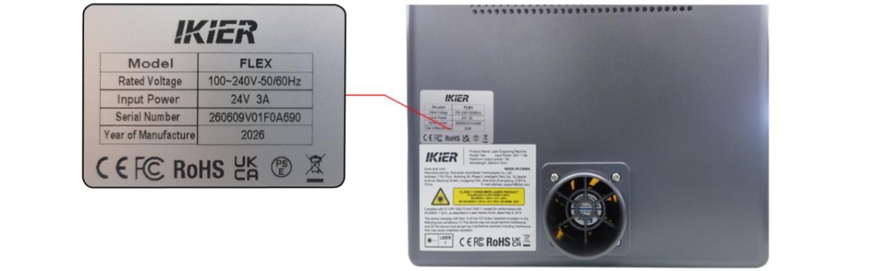
Figure 29
¶ 8. The Software Continually Prompts "USB Key Not Inserted"
Please follow the steps below to troubleshoot the issue:
- Troubleshooting Steps
- Check whether the USB Key is inserted, as shown in Figure 30. Gently move the USB Key and check whether the indicator turns green.
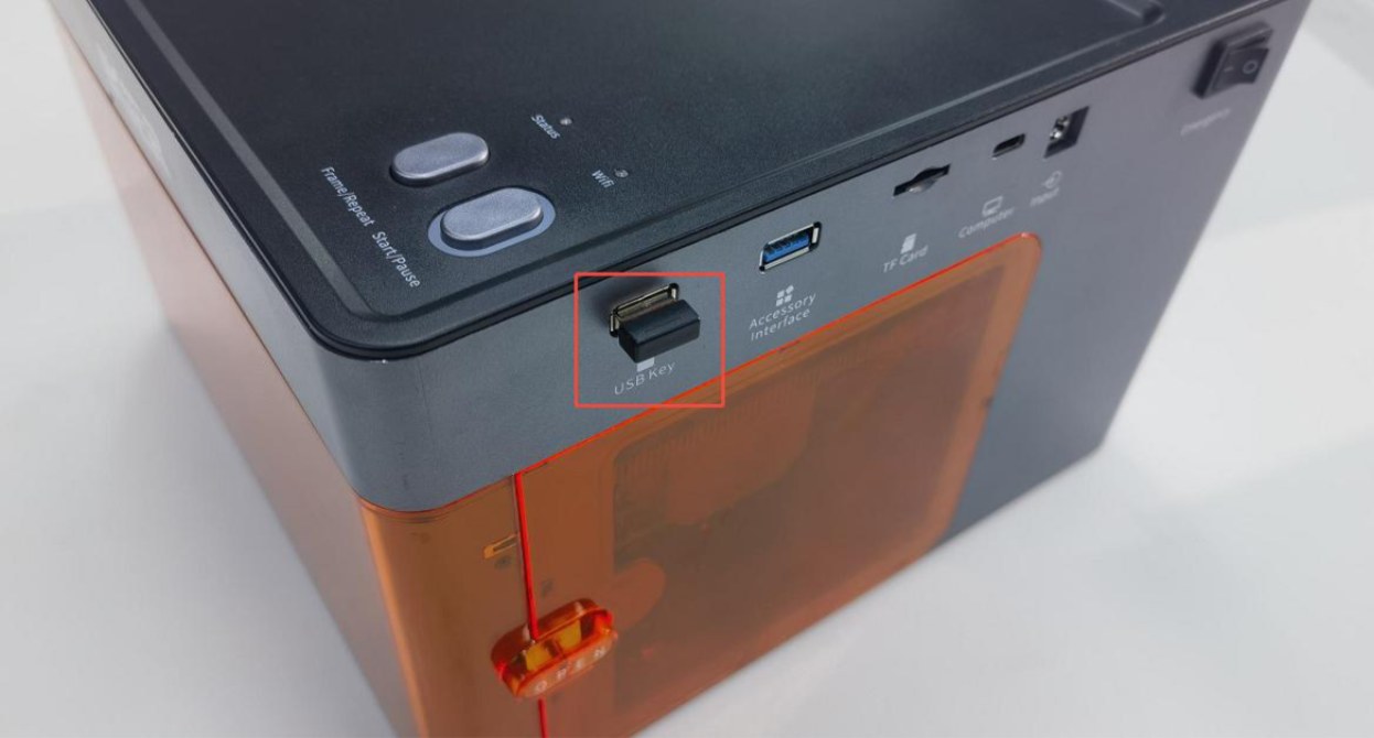
Figure 30
- Check whether the top cover of the enclosure is properly closed (the top cover is equipped with an lid-open detection function). Open and close the top cover again, or press the detection switch by hand (as shown in Figure 31) to check whether the status indicator returns to normal green.
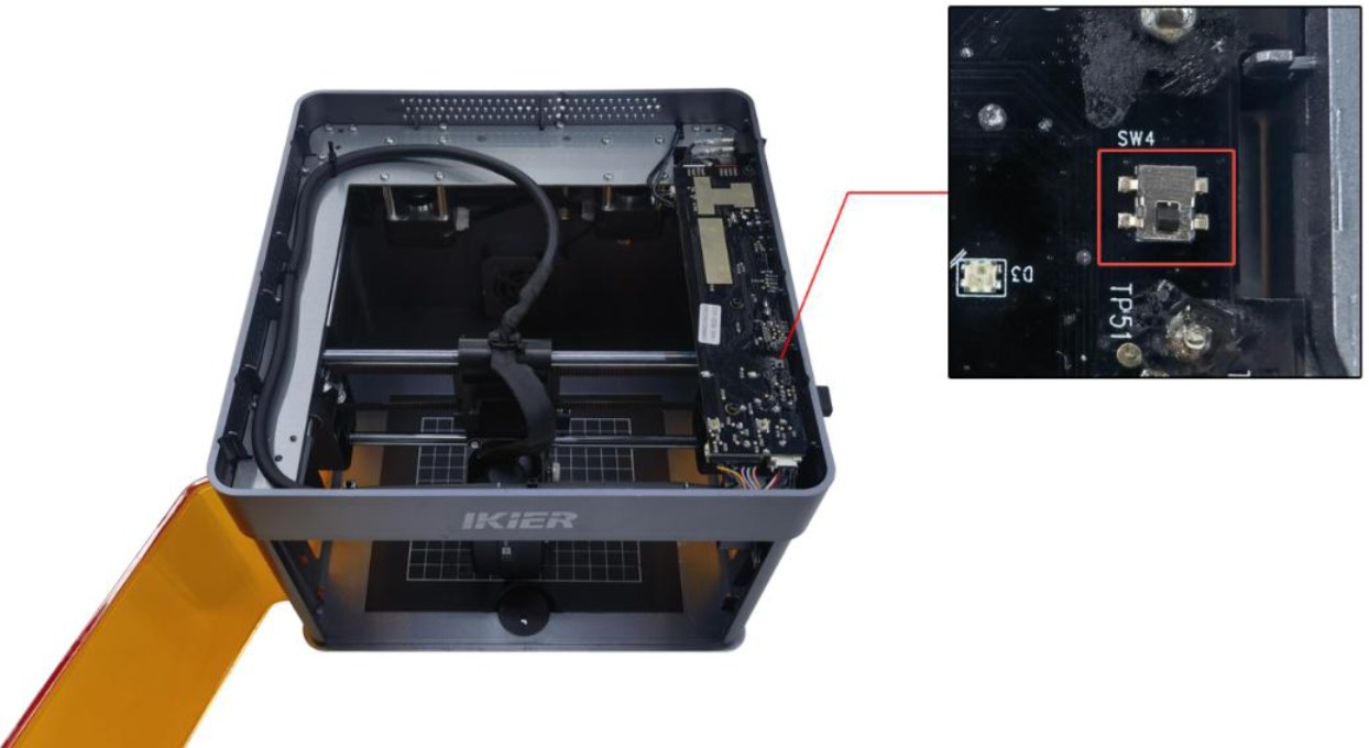
Figure 31
- Contact Customer Service
If you identify a problem during troubleshooting but cannot resolve it yourself, or if the cause of the fault cannot be determined, please provide the following information to Customer Service:
-
Troubleshooting Video: Provide a video showing the operation and the issue.
-
Troubleshooting Steps: Provide a description of the steps that have already been checked or performed.
-
Device Serial Number: Provide a photo of the device Serial Number, as shown in Figure 32.
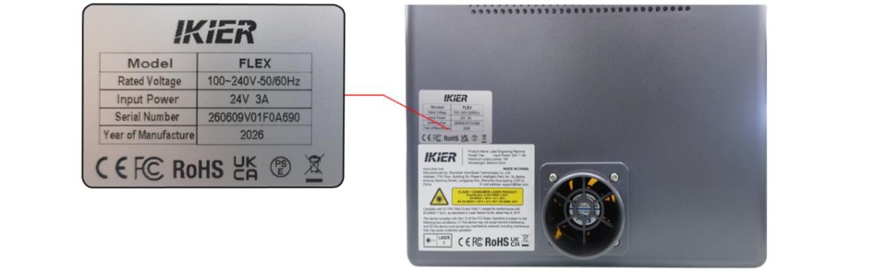
Figure 32
¶ 9. The Laser Protective Window Glass Is Dirty or Damaged
Follow the steps below:
- Dirty
When the laser protective window is dirty, it must be cleaned. Otherwise, it may significantly affect the laser power and may even cause the protective window to become damaged. ① Cleaning Tools
-
Lint-free cloth.
-
Absolute ethanol (purity of 99% or higher is recommended).
② Cleaning Procedure
- Remove the Laser
Turn off the engraving machine, remove the laser, and disconnect the laser cable.
- Clean the Glass
Apply a small amount of absolute ethanol to a lint-free cloth. Wipe the lens gently in a spiral motion from the center outward, moving in a single direction. Avoid wiping back and forth, as this may cause scratches.
- Damaged
The protective window of the 7W laser cannot be repaired. Once damaged, the entire laser must be replaced. The protective window of the 12W laser can be replaced separately. To prevent the protective window from being damaged due to abnormalities such as burned-on stains, refer to the "Laser Maintenance" section and clean the protective window regularly to keep its surface clean.
- Contact Customer Service
If you identify a problem during troubleshooting but cannot resolve it yourself, please provide the following information to Customer Service:
-
Clear Photos: Provide clear photos showing the dirt or damage.
-
Laser Engraved Serial Number: Provide the laser's engraved serial number, as shown in Figure 33.
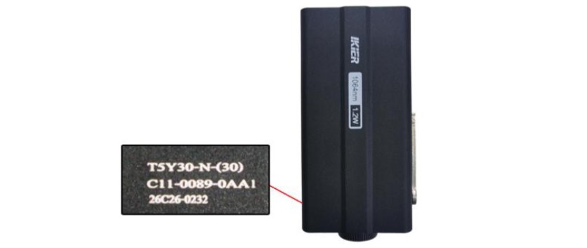
Figure 33
¶ 10. The Laser's Cutting Performance Has Significantly Decreased Compared with Before
Please follow the steps below to troubleshoot the issue:
- Check the Software Parameters
Different materials require different processing parameters. Refer to the parameter table to confirm whether the power, speed, and speed unit are set correctly.
- Check the Material Batch
Different batches of materials may produce different cutting results due to variations in the manufacturing process. It is recommended to:
-
Use materials from the same batch for comparison testing.
-
Alternatively, cut A4 printing paper to determine whether the laser power has significantly decreased.
The recommended parameters for cutting A4 paper are as follows: → Flex 12W: 60% power, 2000 mm/min speed. → Flex 7W: 100% power, 1300 mm/min speed.
- Check the Laser Protective Window
A dirty or damaged protective window can significantly affect the laser output power. Follow the instructions in the "The Laser Window Lens Is Dirty or Damaged" section to troubleshoot the issue.
- Check the Maximum S-Value (LightBurn)
The “S-Value Max”must remain set to“1000”(as shown in Figure 34). Do not change this value, as doing so may affect the laser power and service life.
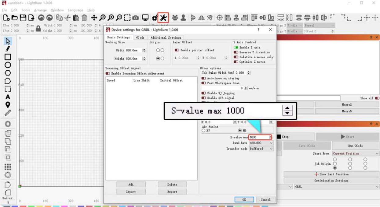
Figure 34
- Check the Power Supply Output
Insufficient voltage or current can directly affect the laser power.
-
Measure the Power Adapter: Set the multimeter to DC voltage mode and measure the output voltage of the power adapter. The output should be 24 V. If an ammeter is available, measure whether the maximum output current of the power adapter reaches 3 A.
-
Measure the Laser Cable: Disconnect the laser cable, run a cutting program at 100% power and a speed of 1
mm/min, and use a multimeter in DC voltage mode to measure whether the voltage between Pins 1 and 2 is 24 V and between Pins 2 and 3 is 5 V, as shown in Figure 35.
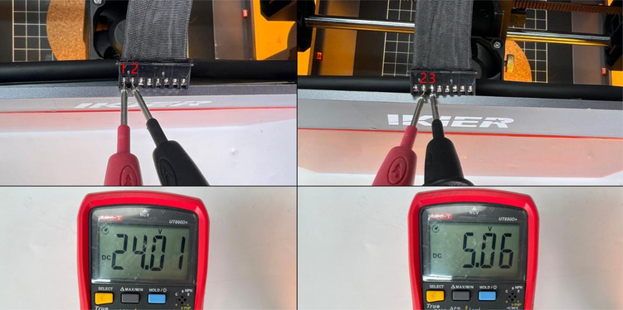
Figure 35
- Contact Customer Service
If you identify a problem during troubleshooting but cannot resolve it yourself, or if the cause of the fault cannot be determined, please provide the following information to Customer Service:
-
Cutting Video: The video must clearly show the set power, speed, material thickness, cutting process, and final result.
-
Troubleshooting Steps: Provide a description of the steps that have already been checked or performed. If voltage measurements were taken, provide the measurement results.
-
Laser Protective Window Photos: Provide clear photos of the protective window.
-
Laser Engraved Serial Number: Provide the laser's engraved serial number, as shown in Figure 36.
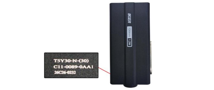
Figure 36
¶ 11. The Laser Head Moves During Engraving but Does Not Emit Laser Light
Please follow the steps below to troubleshoot the issue:
- Confirm That the Focus Is Set Correctly (Infrared Laser)
After placing the material, perform the focusing procedure. If necessary, refer to the "Laser Focusing Instructions" section and refocus the laser. The infrared laser is highly sensitive to the focusing distance, and infrared light is invisible. If the focusing distance is incorrect, you will not be able to see the engraving sparks.
- Check the Laser Cable
Check whether the laser cable is properly connected. Disconnect and reconnect the cable if necessary.
- Check the Mainboard Cable
Open the top cover of the enclosure and check whether the laser cable connected to the mainboard is loose. Disconnect and reconnect the cable if necessary.
- Measure the Voltage of the Laser Cable
- Disconnect the laser cable, run a cutting program at 100% power and a speed of 1 mm/min, and use a multimeter in DC voltage mode to measure whether the voltage between Pins 1 and 2 is 24 V and between Pins 2 and 3 is 5 V, as shown in Figure 37.
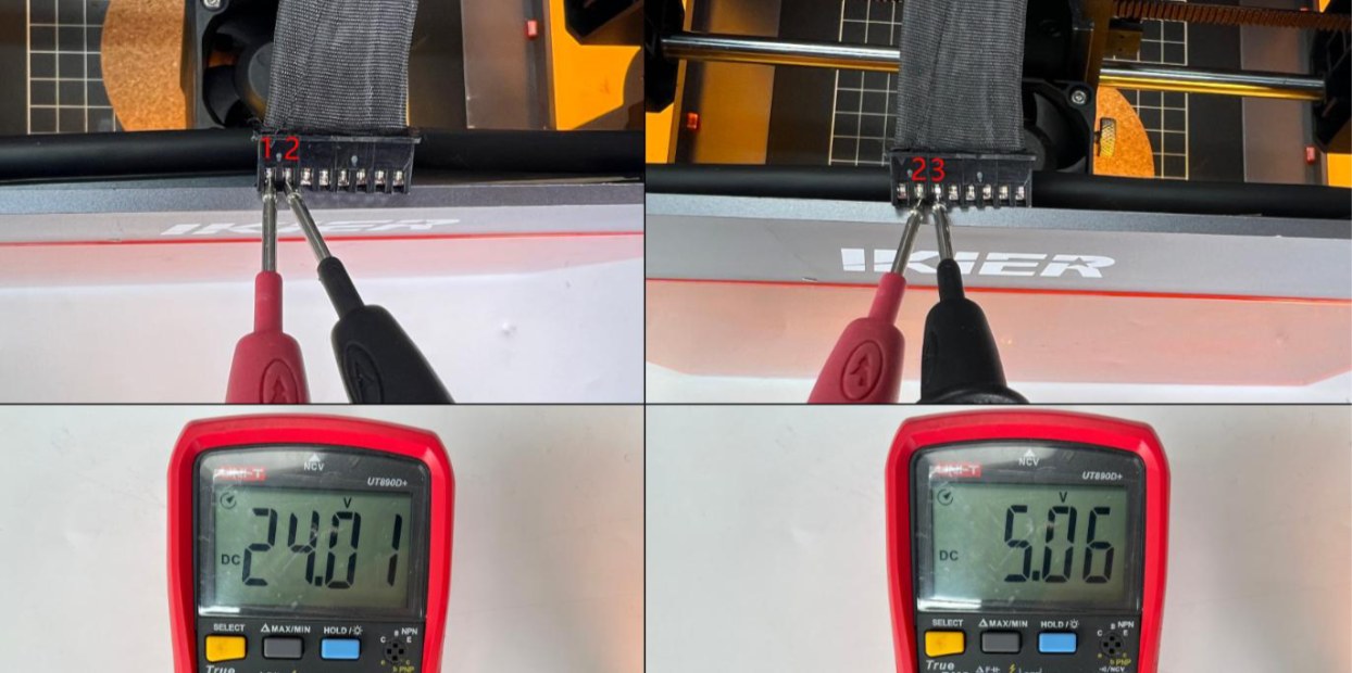
Figure 37
- Contact Customer Service
If you identify a problem during troubleshooting but cannot resolve it yourself, or if the cause of the fault cannot be determined, please provide the following information to Customer Service:
-
Troubleshooting Video.
-
Troubleshooting Steps: Provide a description of the steps that have already been checked or performed. If voltage measurements were taken, provide the measurement results.
-
Laser Engraved Serial Number: Provide the laser's engraved serial number, as shown in Figure 38.
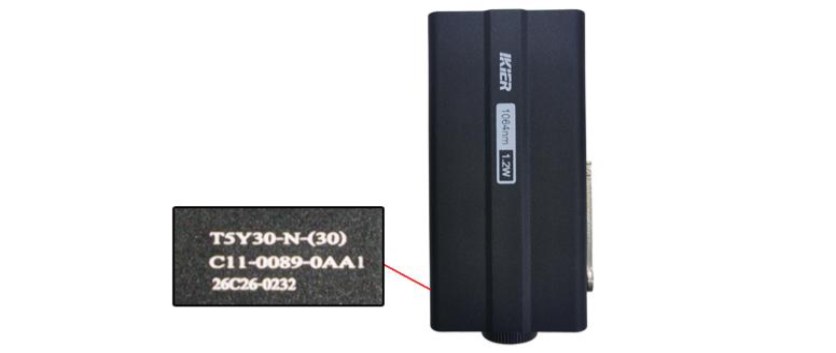
Figure 38
¶ 12. Poor Engraving Results
Please follow the steps below to troubleshoot the issue:
- Confirm That the Focus Is Set Correctly
After placing the material, refocus the laser. Swing down the focusing rod until its end just touches the surface of the material, as shown in Figure 39.
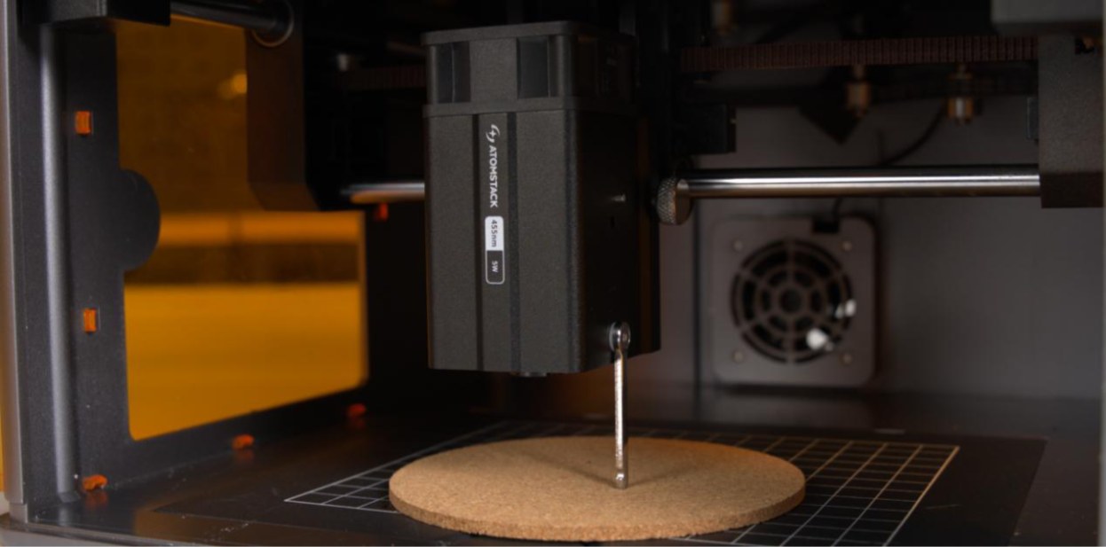
Figure 39
- Check the Software Parameters
Different materials require different processing parameters. Refer to the parameter table to confirm whether the power, speed, and speed unit are set correctly. The parameter table can be accessed by scanning the QR code on the back of the device, or you can contact Customer Service to request it.
- Confirm the S-Value Max (LightBurn)
The S-Value Max must remain set to 1000 (as shown in Figure 40). Do not change this value, as doing so may affect the laser power and service life.
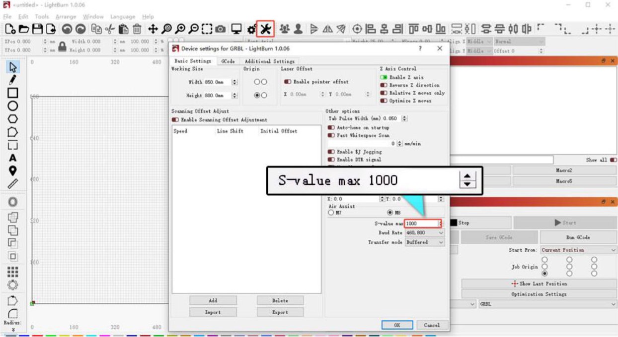
Figure 40
- Check the Protective Window Glass
A dirty or damaged protective window can significantly affect the laser output power. Follow the instructions in the "The Laser Window Glass Is Dirty or Damaged" section to troubleshoot the issue.
- Check the Power Supply Output
Insufficient voltage or current can directly affect the laser power.
-
Measure the Power Adapter: Set the multimeter to DC voltage mode and measure whether the output voltage of the power adapter is 24 V. If an ammeter is available, measure whether the maximum output current of the power adapter reaches 3 A.
-
Measure the Laser Cable: Disconnect the laser cable, run a cutting program at 100% power and a speed of 1
mm/min, and use a multimeter in DC voltage mode to measure whether the voltage between Pins 1 and 2 is 24 V and between Pins 2 and 3 is 5 V, as shown in Figure 41.
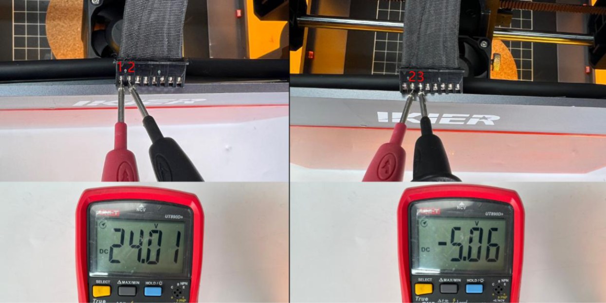
Figure 41
- Power Test
Secure a sheet of A4 paper and perform a cutting test using the recommended parameters below to determine whether the laser power is abnormal. The recommended parameters for cutting A4 paper are as follows: → Flex 12W: 60% power, 2000 mm/min speed. → Flex 7W: 100% power, 1300 mm/min speed.
- Contact Customer Service
If none of the above steps resolve the issue, please contact Customer Service and provide the following information:
-
Engraving Video: The video must clearly show the focusing process, set power, speed, engraving process, and final result.
-
Troubleshooting Steps: Provide a description of the steps that have already been checked or performed. If voltage measurements were taken, provide the measurement results.
-
Cutting Video: Provide a video of the A4 paper cutting test. The video must clearly show the focusing process, set power, speed, cutting process, and final result.
-
Laser Engraved Serial Number: Provide the laser's engraved serial number, as shown in Figure 42.
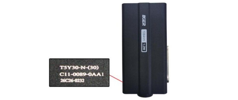
Figure 42
¶ 13. The Engraved Output Pattern Is Distorted
Troubleshoot the issue according to the symptoms below. It is recommended to first engrave a circular or square pattern, and then troubleshoot the issue based on the actual movement trajectory as follows:
- Moving Diagonally at a 45° Angle
- Check the Motor Cable
Disconnect the motor cable and reconnect it. Check whether the issue is resolved.
- Check the Motor Cable on the Mainboard
Open the top cover of the enclosure and locate the motor cable on the side of the mainboard near the power switch (as shown in Figure 43). Make sure that the cable is fully inserted and securely connected. If it is loose, disconnect and reconnect it, ensuring that the connector is firmly seated in the socket.
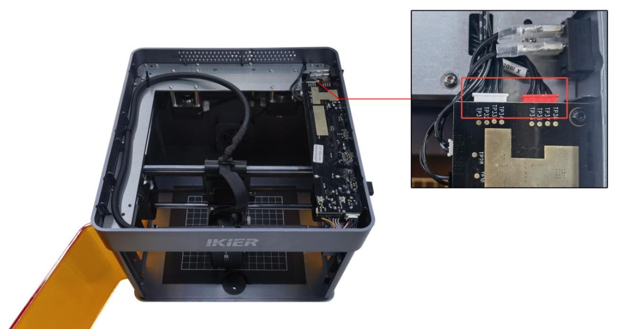
Figure 43
- Check the Timing Pulley and Timing Belt
Check whether the screws on the timing pulley (as shown in Figure 44) are loose and whether the timing belt is too loose.
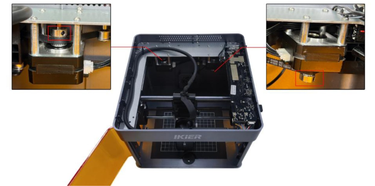
Figure 44
- Note: If the issue persists after tightening the timing pulley screws and adjusting the timing belt, skip directly to Step 3) "Shaking and Moving Diagonally" for further troubleshooting.
- Moving in the Reverse Direction
-
Restore the machine to factory settings.
-
If only the Y-axis moves in the reverse direction, check the motor cable connections on the mainboard. The cable may be connected to the wrong port. The correct position is with the red connector closer to the power switch, as shown in Figure 45.
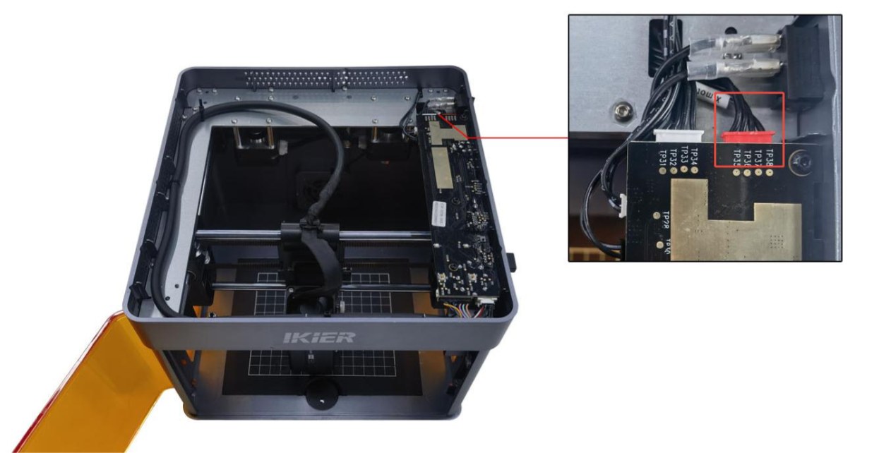
Figure 45
- Shaking and Moving Diagonally
-
The machine moves only toward the upper-left or lower-right corner: This indicates an abnormality with the left motor. Disconnect both motor cables and connect the left motor cable (the longer cable) to the right-side motor. Use the controls to move the laser head and check whether it can move normally toward the upper-left or lower-right corner without shaking. → If the movement is normal: The left motor is faulty. → If the movement is still abnormal: The motor cable or the mainboard motor driver may be faulty.
-
The machine moves only toward the upper-right or lower-left corner: This indicates an abnormality with the right motor. Disconnect both motor cables and connect the left motor cable (the longer cable) to the right-side motor. Use the controls to move the laser head and check whether it can move normally toward the upper-right or lower-left corner without shaking. → If the movement is normal: The motor cable or the mainboard motor driver may be faulty. → If the movement is still abnormal: The motor may be faulty.
- Check the Material
When processing lightweight materials (such as paper or thin wood boards), use magnets to secure all four corners. Otherwise, the material may be moved by the enclosure exhaust fan or laser fan, causing the output pattern to shift or become distorted.
- Confirm the Firmware Version
After connecting the machine, click "≡" in the upper-right corner to check the firmware version, as shown in Figure 46. Send a screenshot of the version number to Customer Service to confirm whether it is the latest version.
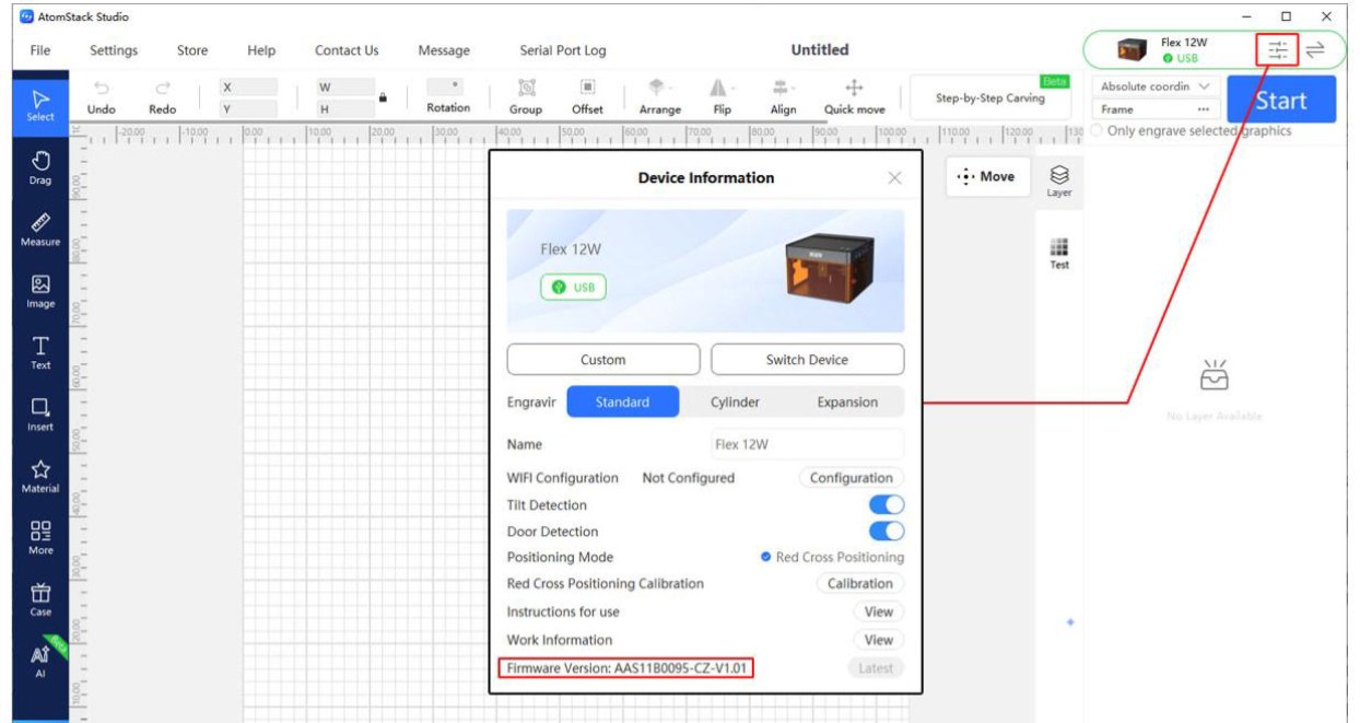
Figure 46
- Check the Mechanical Structure
If the engraved circle or square is irregular in shape, the issue may be related to the mechanical structure of the machine. Check the following components in sequence:
-
Check the Timing Pulleys: Check whether the timing pulley screws are loose and whether the timing pulley position is offset, as shown in Figure 47. Adjust if necessary.
-
Check the Timing Belt: Press the timing belt by hand to check whether it is too loose. If it is loose, adjust it.
-
Check the Guide Rollers: Check whether all guide rollers along the timing belt path are working properly.
Make sure there are no timing belt abrasion debris inside the enclosure.
- Check the Guide Rails: Check that the surfaces of all three guide rails are free of scratches and that they are adequately lubricated.
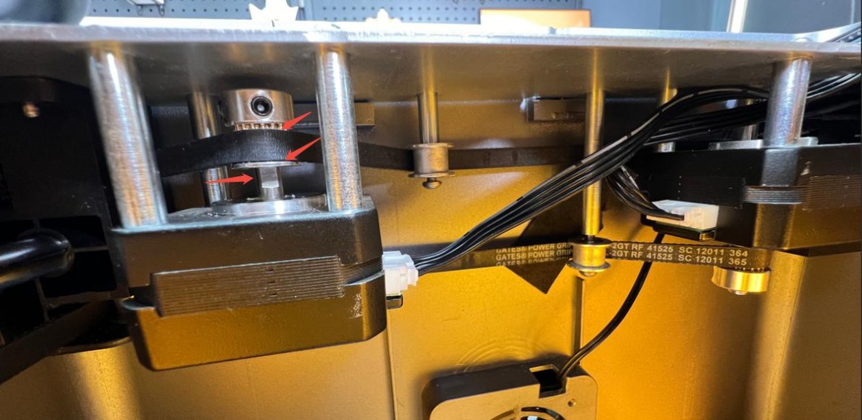
Figure 47
- Restore Factory Settings
If none of the above steps resolve the issue, restore the machine to factory settings and rule out abnormal parameter settings as a possible cause.
- Contact Customer Service
If none of the above steps resolve the issue, please contact Customer Service and provide the following information:
-
Engraving Video: The video must clearly show the focusing process, set power, speed, engraving process, and final result.
-
Troubleshooting Steps: Provide a description of the steps that have already been checked or performed.
-
Firmware Version: Provide a screenshot showing the firmware version.
-
Device Serial Number: Provide a photo of the device Serial Number, as shown in Figure 48.
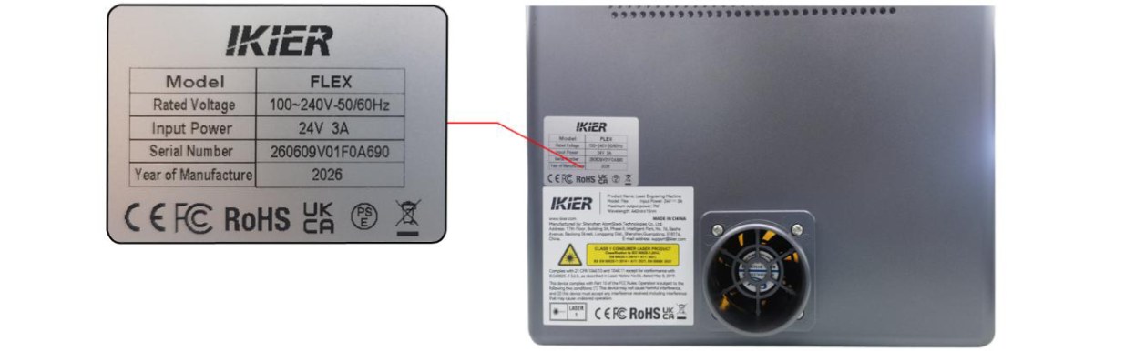
Figure 48
¶ 14. The Engraved Output Pattern Is Reversed
Please follow the steps below to troubleshoot the issue:
- Check the Software and Firmware Versions
Confirm that both the software version and the engraving machine's firmware version are up to date. If an update is available, update the software and firmware before testing again.
- Check the Motor Cable Connection on the Mainboard
Open the top cover of the enclosure and check whether the motor cable is connected to the correct port on the mainboard. The red connector should be positioned closer to the power switch, as shown in Figure 49. If the cable is connected in the wrong orientation, disconnect and reconnect it in the correct orientation.
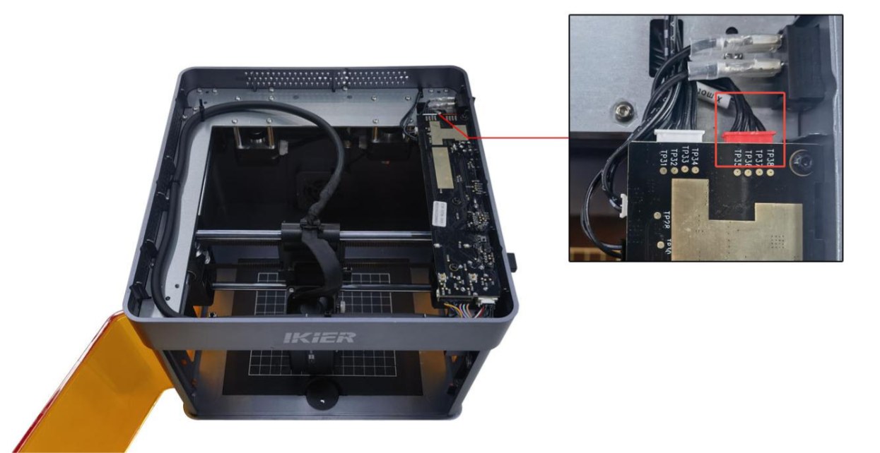
Figure 49
- Restore Factory Settings
If the above steps do not resolve the issue, restore the machine to factory settings and rule out abnormal parameter settings as a possible cause.
¶ 15. The Engraved Output Pattern Is Skewed at a 45° Angle
Please follow the steps below to troubleshoot the issue:
- Check the Timing Pulley Screws and Timing Belt
Check whether the motor timing pulley screws (as shown in Figure 50) are loose and whether the timing belt is too loose. If so, tighten the screws or adjust the timing belt as needed.
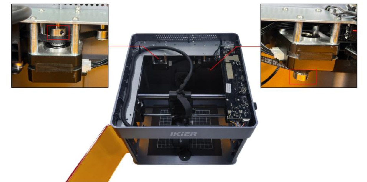
Figure 50
- Check the Motor Cable
Disconnect the motor cable and reconnect it. Check whether the issue is resolved.
- Check the Motor Cable Connection on the Mainboard
Open the top cover of the enclosure and locate the motor cable on the side of the mainboard near the power switch (as shown in Figure 51). Make sure that the cable is fully inserted and securely connected. If it is loose, disconnect and reconnect it, ensuring that the connector is firmly seated in the socket.
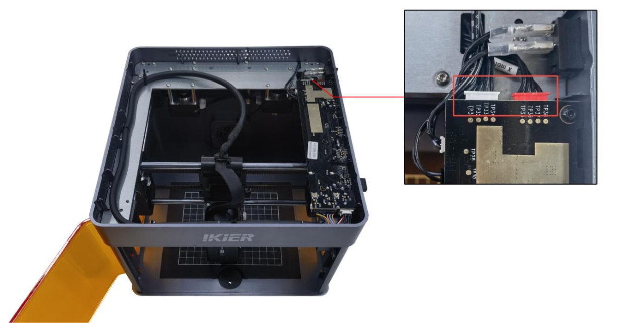
Figure 51
- Check the Motor
-
The machine moves only toward the upper-left or lower-right corner: This indicates an abnormality with the left motor. Disconnect both motor cables and connect the left motor cable (the longer cable) to the right-side motor. Use the controls to move the laser head and check whether it can move normally toward the upper-left or lower-right corner without shaking. → If the movement is normal: The left motor is faulty. → If the movement is still abnormal: The motor cable or the mainboard motor driver may be faulty.
-
The machine moves only toward the upper-right or lower-left corner: This indicates an abnormality with the right motor. Disconnect both motor cables and connect the left motor cable (the longer cable) to the right-side motor. Use the controls to move the laser head and check whether it can move normally toward the upper-right or lower-left corner without shaking. → If the movement is normal: The motor cable or the mainboard motor driver may be faulty. → If the movement is still abnormal: The motor may be faulty.
- Contact Customer Service
If none of the above steps resolve the issue, please contact Customer Service and provide the following information:
-
Troubleshooting Video: Clearly show the software operation steps and the direction in which the laser head moves.
-
Troubleshooting Steps: Provide a description of the steps that have already been checked or performed.
-
Device Serial Number: Provide a photo of the device Serial Number, as shown in Figure 52.
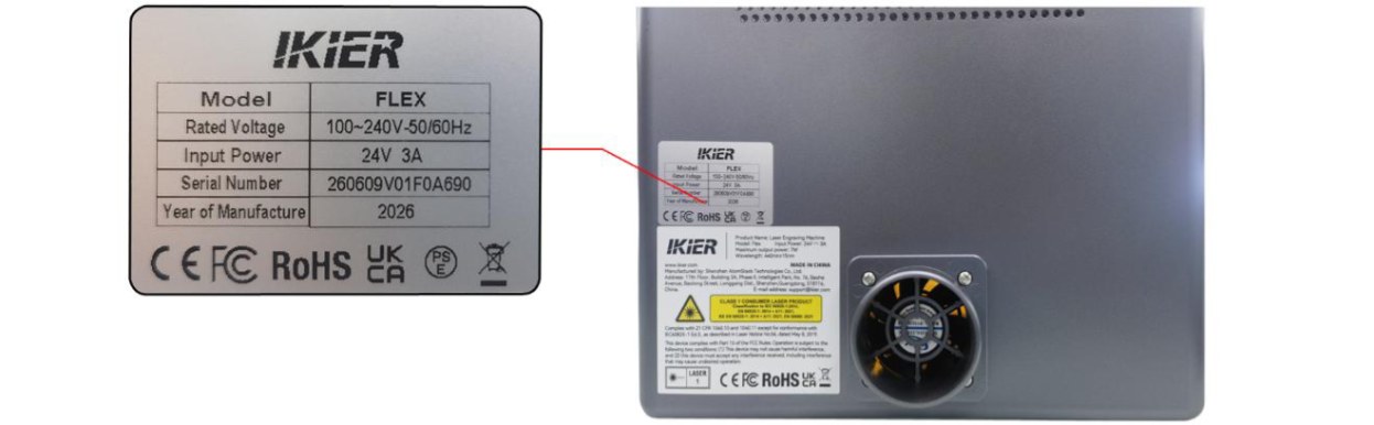
Figure 52
¶ 16. The Laser Head Only Moves at a 45° Angle and Cannot Move Normally Up, Down, Left, or Right
Please follow the steps below to troubleshoot the issue:
- Check the Timing Pulley Screws and Timing Belt
Check whether the motor timing pulley screws (as shown in Figure 53) are loose and whether the timing belt is too loose. If so, tighten the screws or adjust the timing belt as needed.
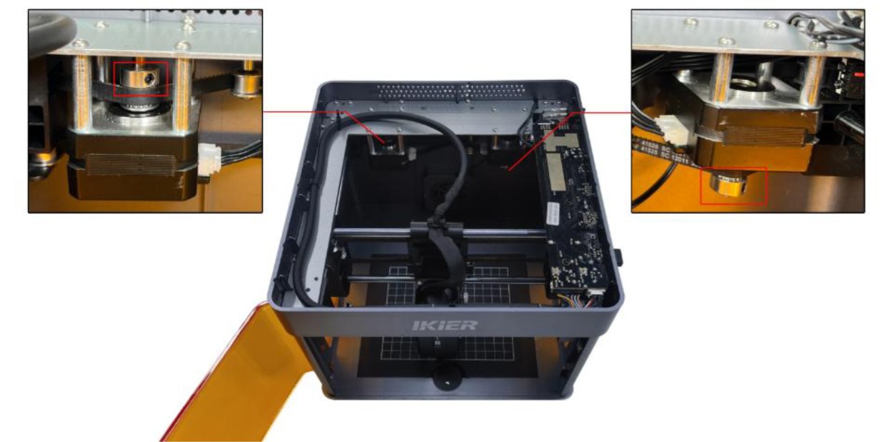
Figure 53
- Check the Motor Cable
Disconnect the motor cable and reconnect it. Check whether the issue is resolved.
- Check the Motor Cable Connection on the Mainboard
Open the top cover of the enclosure and locate the motor cable on the side of the mainboard near the power switch (as shown in Figure 54). Make sure that the cable is fully inserted and securely connected. If it is loose, disconnect and reconnect it, ensuring that the connector is firmly seated in the socket.
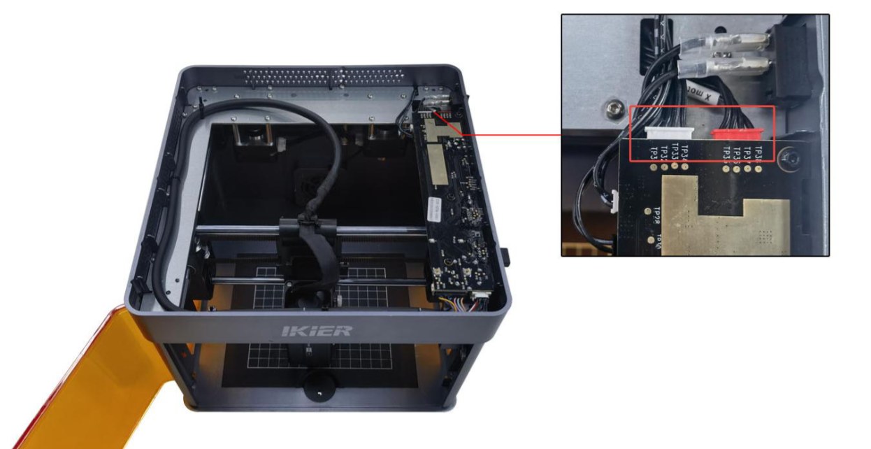
Figure 54
- Check the Motor
-
The machine moves only toward the upper-left or lower-right corner: This indicates an abnormality with the left motor. Disconnect both motor cables and connect the left motor cable (the longer cable) to the right-side motor. Use the controls to move the laser head and check whether it can move normally toward the upper-left or lower-right corner without shaking. → If the movement is normal: The left motor is faulty. → If the movement is still abnormal: The motor cable or the mainboard motor driver may be faulty.
-
The machine moves only toward the upper-right or lower-left corner: This indicates an abnormality with the right motor. Disconnect both motor cables and connect the left motor cable (the longer cable) to the right-side motor. Use the controls to move the laser head and check whether it can move normally toward the upper-right or lower-left corner without shaking. → If the movement is normal: The motor cable or the mainboard motor driver may be faulty. → If the movement is still abnormal: The motor may be faulty.
- Contact Customer Service
If none of the above steps resolve the issue, please contact Customer Service and provide the following information:
-
Troubleshooting Video: Clearly show the software operation steps and the direction in which the laser head moves.
-
Troubleshooting Steps: Provide a description of the steps that have already been checked or performed.
-
Device Serial Number: Provide a photo of the device Serial Number, as shown in Figure 55.
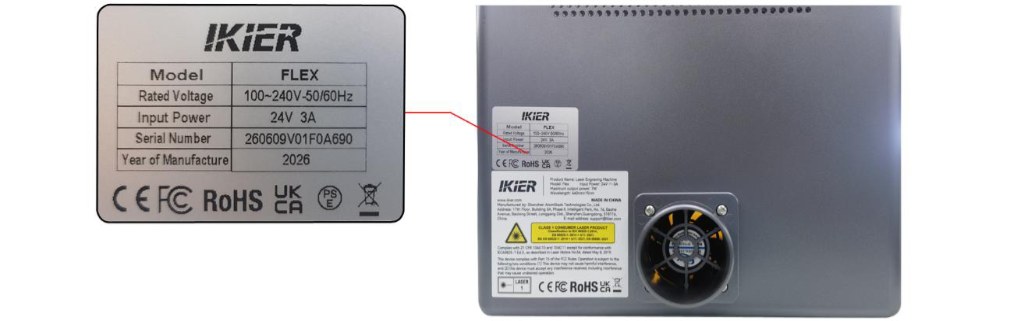
Figure 55
¶ 17. The Machine Suddenly Stops During Engraving
Please follow the steps below to troubleshoot the issue:
- Check for Software Alarm Messages
When this issue occurs, check whether the software displays any relevant alarm message, and troubleshoot the issue according to the alarm message: ① USB Key Not Connected
- Check whether the USB Key is inserted, as shown in Figure 56. Gently move the USB Key and check whether the indicator turns green.
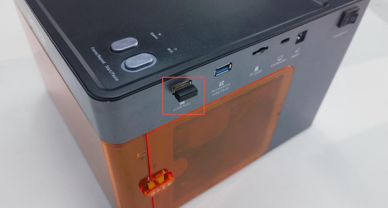
Figure 56
- Check whether the lid of the enclosure is properly closed (the lid is equipped with a lid-open detector).
Open and close the top cover again. Alternatively, press the detection switch by hand (as shown in Figure 57) and check whether the status indicator returns to normal green.
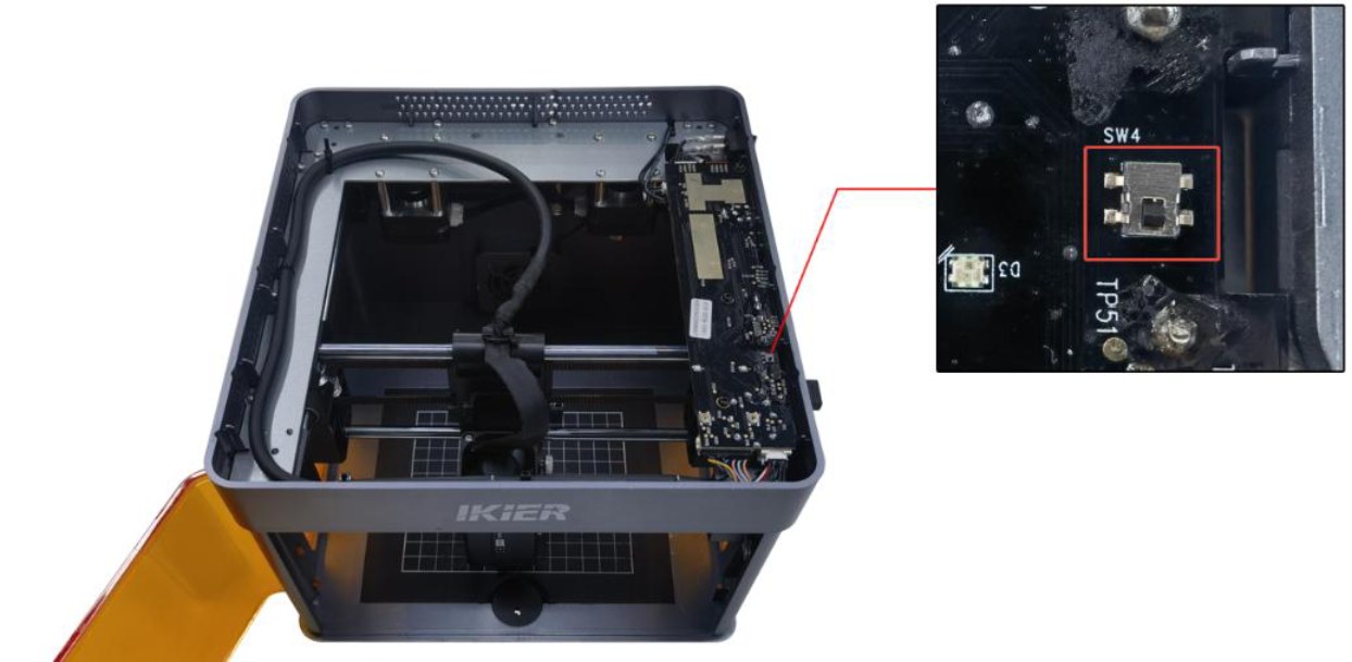
Figure 57
② Abnormal Enclosure Opening
-
Check whether the enclosure door is fully closed. Open and close the door again.
-
Press the two limit switch trigger points on the enclosure door by hand and check whether the status indicator returns to normal green. → Returns to normal green after pressing: The enclosure door was not fully closed. Check whether any foreign objects are obstructing the door. → Alarm persists after pressing: Check whether the enclosure door detection limit switch and the connector on the mainboard are loose. Disconnect and reconnect the connector. ③ Limit Switch Triggered by Collision Move the laser head to the center of the enclosure by hand and check whether the indicator turns green. If the machine still indicates that a limit switch has been triggered by a collision, press the X-axis limit switch and Y-axis limit switch by hand in sequence (as shown in Figure 58) and check whether an alarm sound (beeping) is triggered to determine whether the limit switch is damaged.
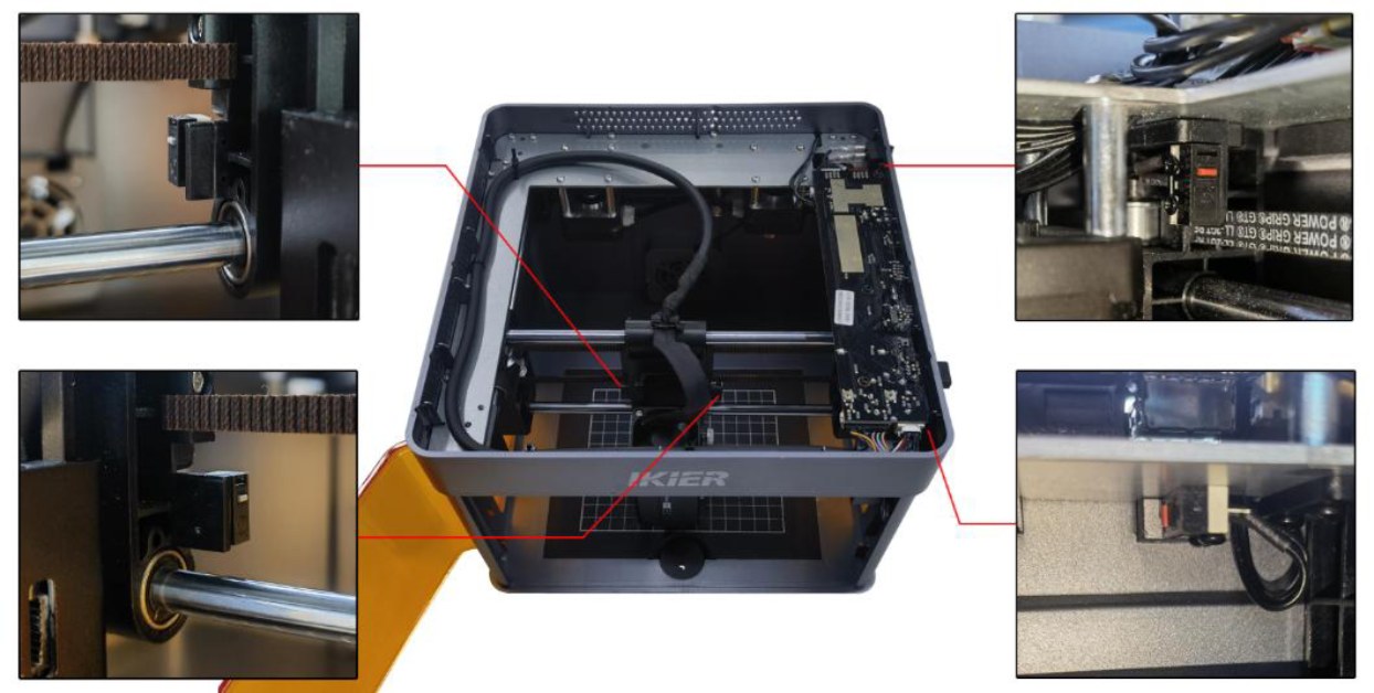
Figure 58
④ Tilt Alarm Make sure that the engraving machine is placed on a level surface. If the alarm persists, open the top cover of the enclosure and tighten the fixing screw next to the buzzer on the mainboard, as shown in Figure 59.
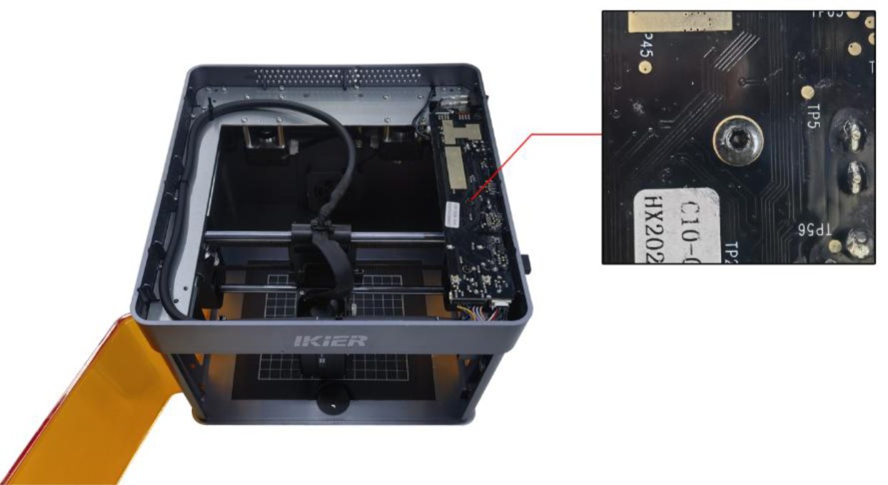
Figure 59
- Check the Type-C Data Cable Connection
-
Make sure that the Type-C data cable is securely connected. Disconnect and reconnect the cable, or try using a different USB port on the computer.
-
Make sure that the Type-C data cable is not touched or moved during engraving to prevent communication interruptions.
- Check the Computer Operating System
If you are using Windows 11, do not switch the software to run in the background during engraving, as the operating system may restrict background communication and cause the machine to stop.
- Try Different Control Software
AtomStack Studio or LightBurn is recommended. Try using a different software program and check whether the issue recurs to rule out software version issues.
- Try a Different Power Adapter
Try using another 24 V power adapter and check whether the issue recurs to rule out unstable power supply from the adapter.
- Contact Customer Service
If none of the above steps resolve the issue, please contact Customer Service and provide the following information:
-
Troubleshooting Video: If the issue can be easily reproduced, record a complete video of the operation. If the issue occurs only after a long period of operation, record the fault condition when the machine stops and the information displayed in the software console.
-
Troubleshooting Steps: Provide a description of the steps that have already been checked or performed.
-
Serial Number: Provide a photo of the Serial Number on the back of the enclosure, as shown in Figure 60.
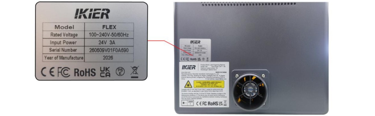
Figure 60
¶ 18. The Software Prompts "Engraving Area Exceeded"
Please follow the steps below to troubleshoot the issue:
- Check the Engraving File Size
Check whether the current engraving file is completely within the engraving area. Make sure there are no patterns outside the engraving area or accidentally selected elements that extend beyond the engraving area.
- Confirm the Selected Coordinate Mode
-
Absolute Coordinates: As long as the file is within the engraving area, this alarm is generally not triggered.
-
Current Position: The laser head must be manually moved or controlled by the software to a suitable position. Make sure sufficient space is reserved for the engraving path; otherwise, the alarm may be triggered. When using“Current Position”mode, it is recommended to use the Framing function before engraving to confirm that the file size is appropriate and the engraving path is within the available area.
- Check the Software Alarm Message
-
X-axis alarm: Check whether the laser head has triggered the left or right limit switch (reached the edge).
-
Y-axis alarm: Check whether the laser head has triggered the front or rear Y-axis limit switch on the right side (reached the edge).
- Manually Trigger the Limit Switches for Verification
Press the limit switches on the left and right sides of the laser head and the front/rear Y-axis limit switches on the right side by hand, as shown in Figure 61. Check whether the alarm sound (beeping) is triggered normally.
-
If a limit switch cannot be triggered, check whether its cable is loose.
-
If the cable is properly connected but the limit switch still cannot be triggered, the limit switch itself may be damaged.
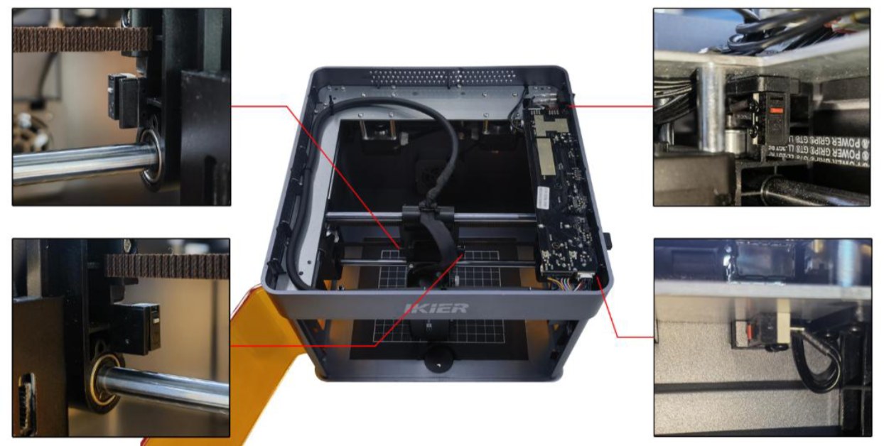
Figure 61
- Check the Mainboard Cables
Open the enclosure lid and check the limit switch cables on the mainboard for looseness, breaks, or poor contact, as shown in Figure 62.
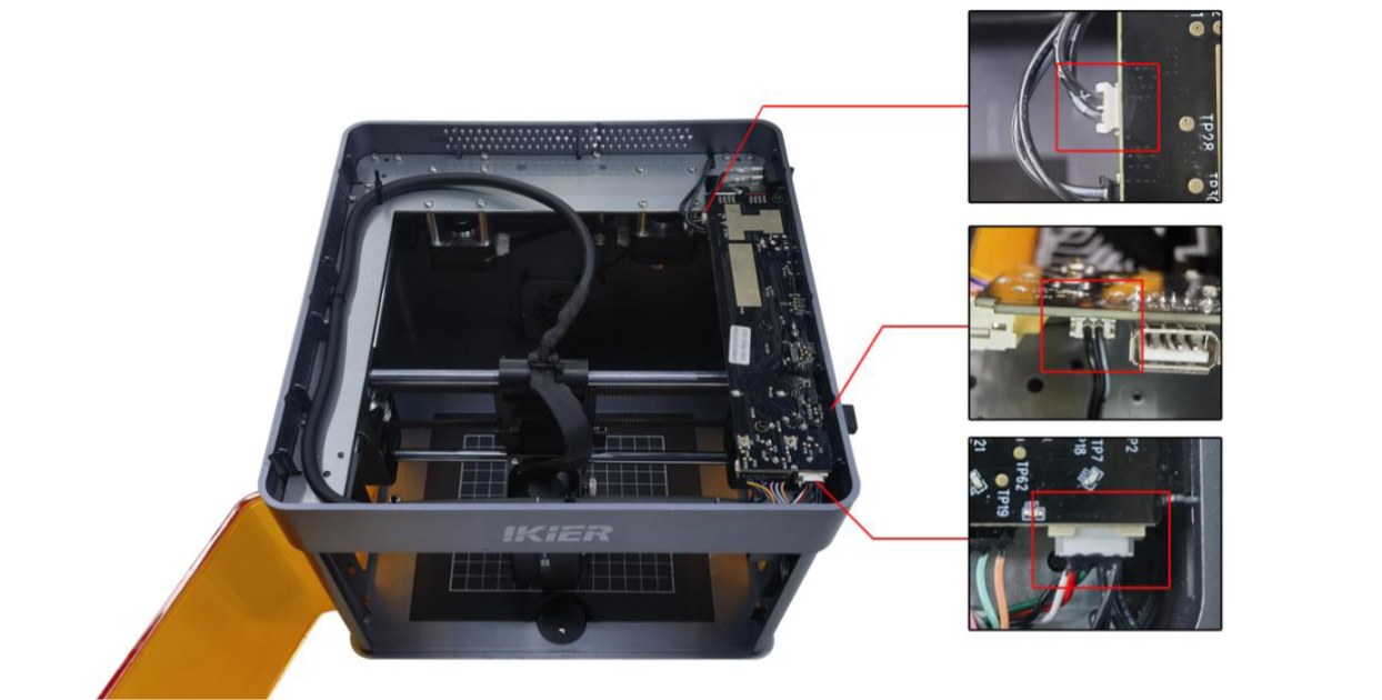
Figure 62
- Restore Factory Settings
If none of the above steps resolve the issue, restore the machine to factory settings and rule out abnormal parameter settings as a possible cause.
- Contact Customer Service
If none of the above steps resolve the issue, please contact Customer Service and provide the following information:
-
Troubleshooting Video: If the issue can be easily reproduced, record a complete video of the operation. If the issue occurs only after a long period of operation, record the fault condition when the alarm appears and the information displayed in the software console.
-
Troubleshooting Steps: Provide a description of the steps that have already been checked or performed.
-
Fault Photos: If a specific fault is identified during troubleshooting, provide clear photos showing the issue.
-
Serial Number: Provide a photo of the Serial Number on the back of the enclosure, as shown in Figure 63.
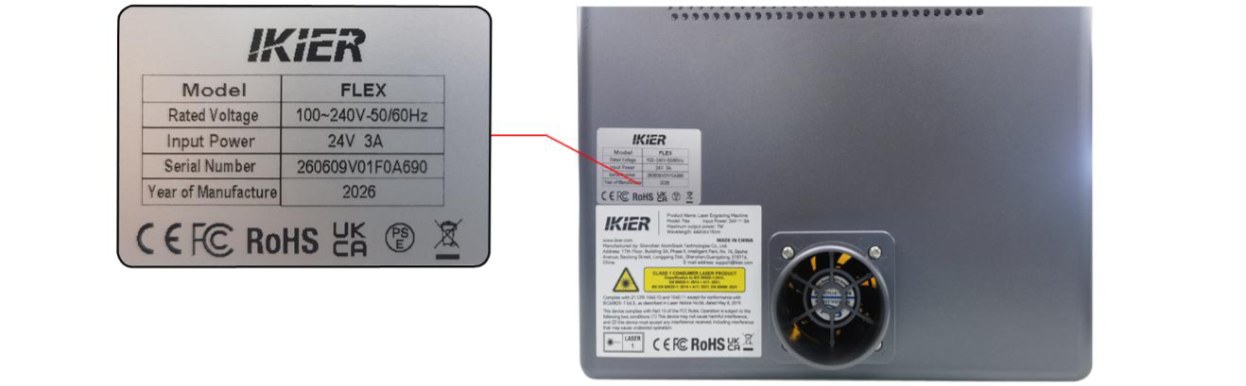
Figure 63
¶ 19. The Laser Head Triggers an Alarm and Prompts "Engraving Area Exceeded" Even When It Is in the Center of the Working Area
Please follow the steps below to troubleshoot the issue:
- Manually Trigger the Limit Switches for Verification
Press the limit switches on the left and right sides of the laser head and the front/rear Y-axis limit switches on the right side by hand, as shown in Figure 64. Check whether the alarm sound (beeping) is triggered normally.
-
If a limit switch cannot be triggered, check whether its cable is loose.
-
If the cable is properly connected but the limit switch still cannot be triggered, the limit switch itself may be damaged.
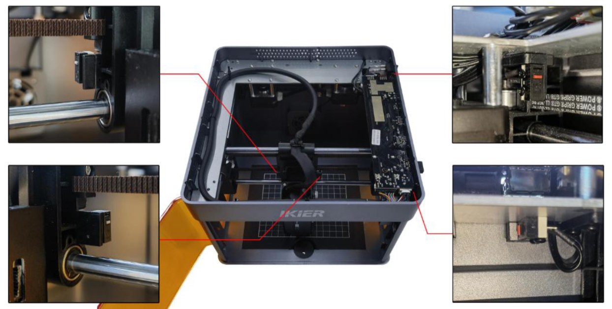
Figure 64
- Check the Mainboard Cables
Open the lid of the enclosure and check the limit switch cables on the mainboard for looseness, breaks, or poor contact, as shown in Figure 65.
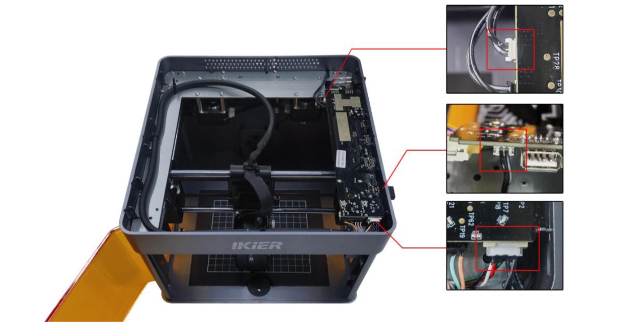
Figure 65
- Restore Factory Settings
If none of the above steps resolve the issue, restore the machine to factory settings and rule out abnormal parameter settings as a possible cause.
- Contact Customer Service
If none of the above steps resolve the issue, please contact Customer Service and provide the following information:
-
Troubleshooting Video: If the issue can be easily reproduced, record a complete video of the operation. If the issue occurs only after a long period of operation, record the fault condition when the alarm appears and the information displayed in the software console.
-
Troubleshooting Steps: Provide a description of the steps that have already been checked or performed.
-
Fault Photos: If a specific fault is identified during troubleshooting, provide clear photos showing the issue.
-
Serial Number: Provide a photo of the Serial Number on the back of the enclosure, as shown in Figure 66.
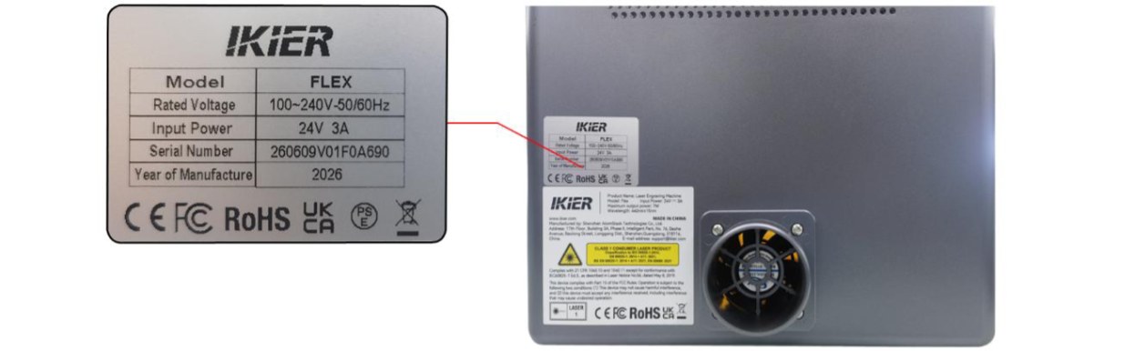
Figure 66
¶ 20. The Software Displays "Limit Switch Not Detected"
Please follow the steps below to troubleshoot the issue:
- Manually Test the Limit Switches
Press the limit switches on both sides of the laser module, as well as the front and rear Y-axis limit switches on the right side (see Figure 67). Check whether the alarm sound (beep) is triggered correctly.
-
If a switch does not trigger the alarm, check whether its cable connection is loose.
-
If the cable is properly connected but the switch still does not respond, the limit switch may be damaged.
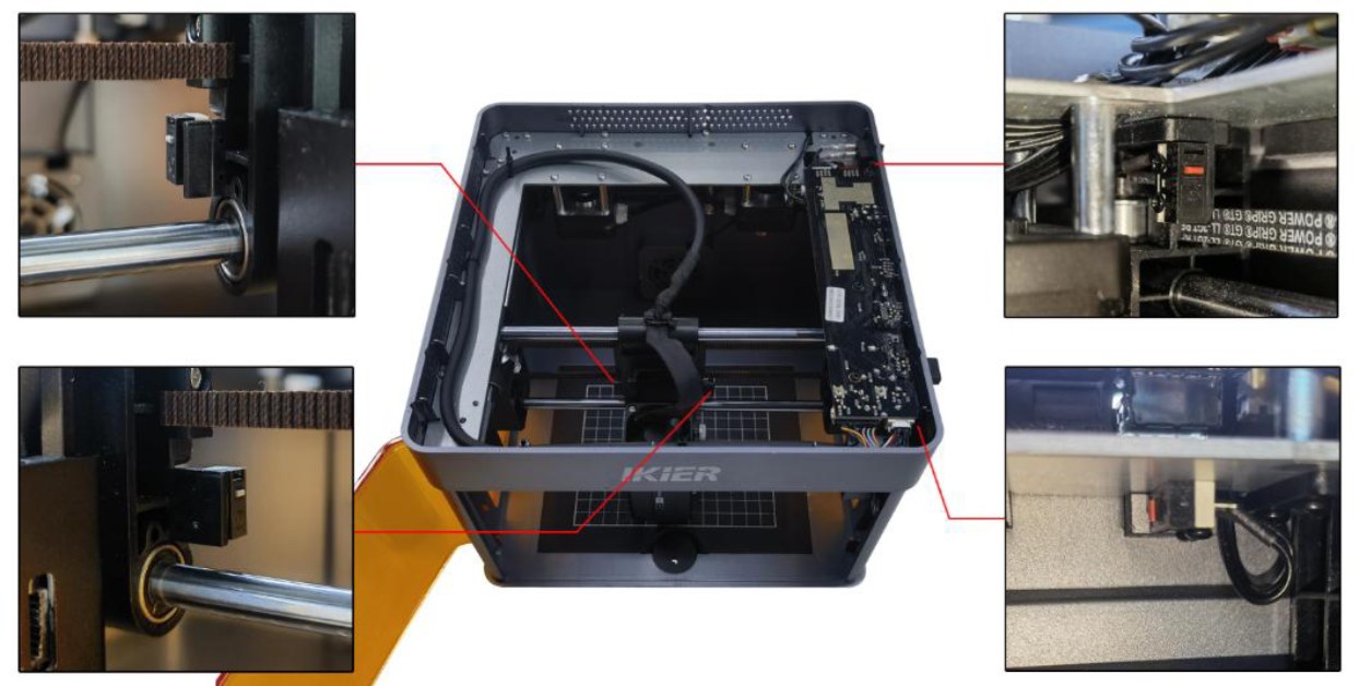
Figure 67
- Check the Mainboard Connections
Open the enclosure lid and inspect the limit switch cables connected to the mainboard. Check for loose connections, damaged wires, or poor contact (see Figure 68).
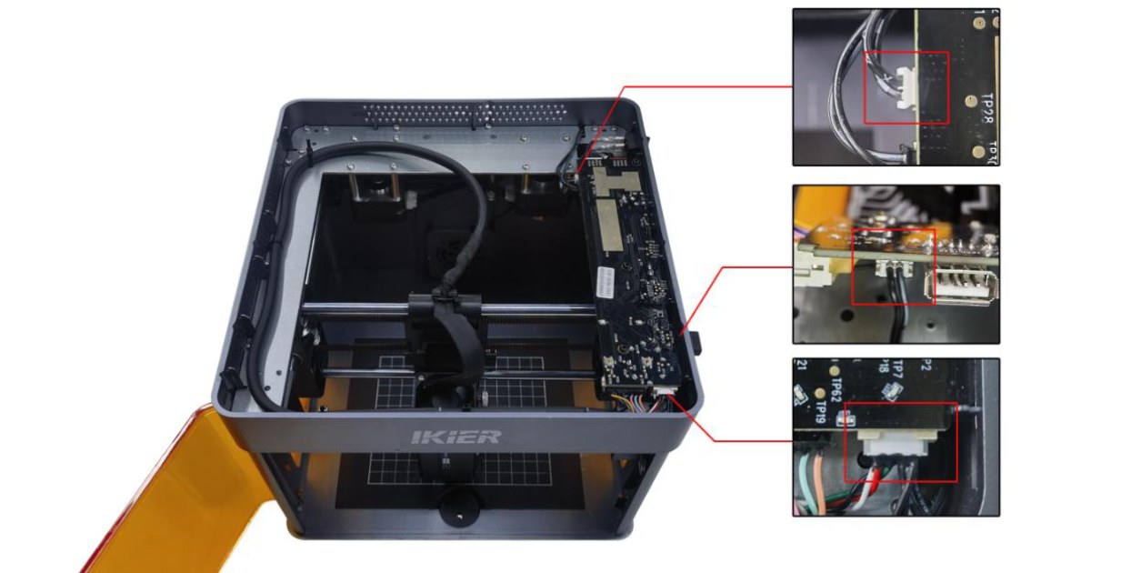
Figure 68
- Restore Factory Settings
If none of the above steps resolve the issue, restore the machine to factory settings and rule out abnormal parameter settings as a possible cause.
- Contact Customer Support
If the problem still cannot be resolved, please contact Customer Support and provide the following information:
- Fault video:
- If the issue can be reproduced easily, record the complete troubleshooting process. * If the issue occurs only occasionally, record the alarm condition and the error code displayed in the software.
-
A description of the troubleshooting steps you have already performed.
-
If a fault is identified during troubleshooting, provide clear photos of the faulty part.
-
A photo of the Serial Number label on the back of the machine (see Figure 69).
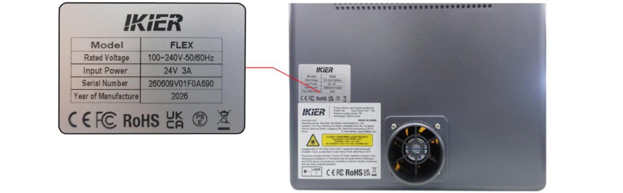
Figure 69
¶ 21. The Enclosure Door Is Closed, but the Software Still Indicates That the Door Is Not Closed
Follow the steps below to troubleshoot the issue:
- Close the Enclosure Door Again
Try closing the enclosure door again and check whether the alarm is cleared.
- Manually Trigger the Limit Switches
Press the two limit switch trigger points on the enclosure door with your fingers, as shown in Figure 70. Check whether the status indicator changes from red to green.
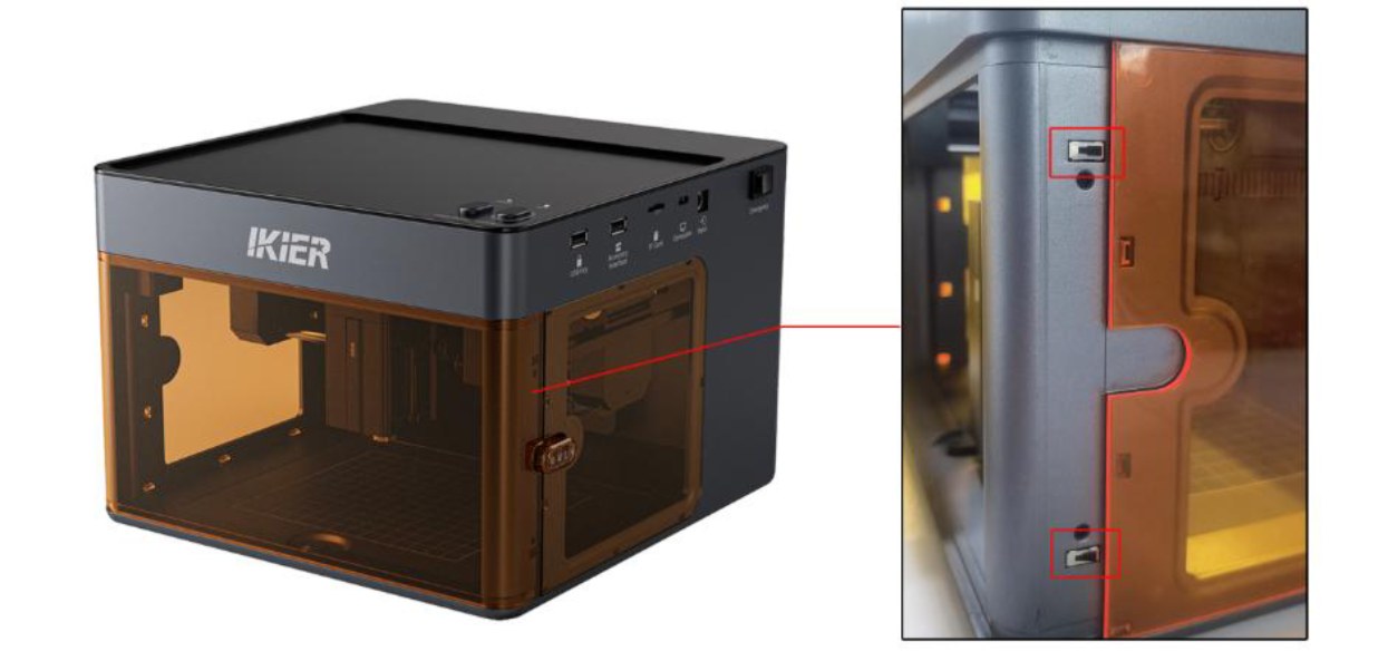
Figure 70
- Check the Cable Connections
- Check the cable connections: Check whether the cables connected to the limit switches and the mainboard are loose, as shown in Figures 71. You can disconnect the cables and then reconnect them to see if the issue is resolved.
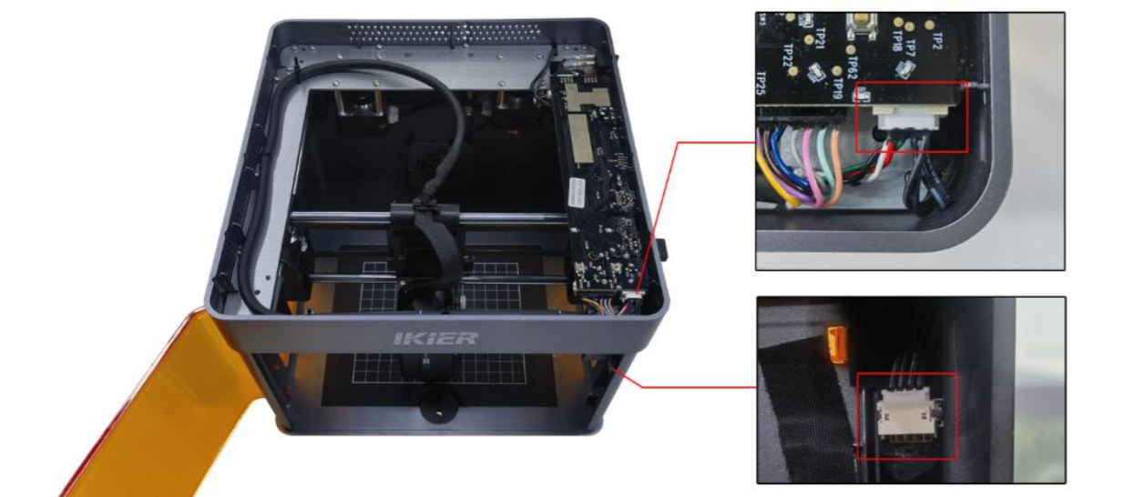
Figure 71
- Measure the cable voltage: Set the multimeter to the DC voltage mode and measure the voltage between pins 1 and 2 and between pins 2 and 3. Both measurements should be 3.3 V, as shown in Figure 72.
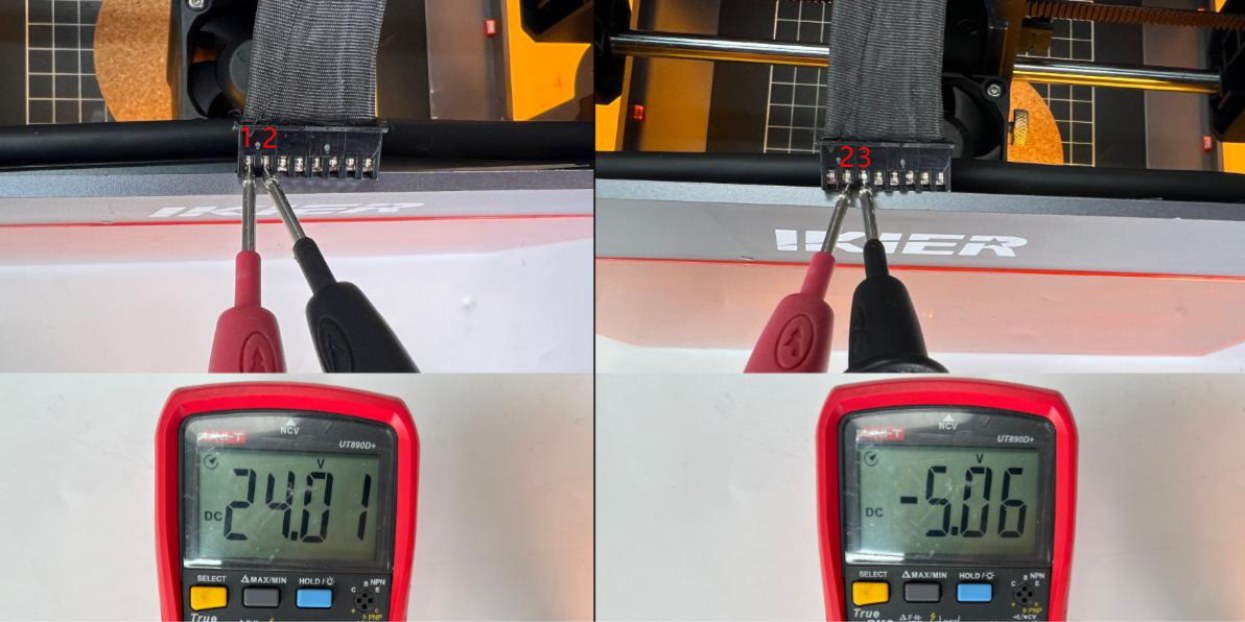
Figure 72
- Restore Factory Settings
If the issue persists after completing the above steps, restore the machine to its factory settings and eliminate the possibility of incorrect parameter settings.
- Contact Customer Support
If the problem still cannot be resolved, please contact Customer Support and provide the following information:
-
Fault video: Show the alarm status and the troubleshooting steps performed, including closing the enclosure door again and checking the cable connections.
-
If a fault is identified during troubleshooting, provide clear photos of the faulty part.
-
A photo of the Serial Number label on the back of the machine (see Figure 73).
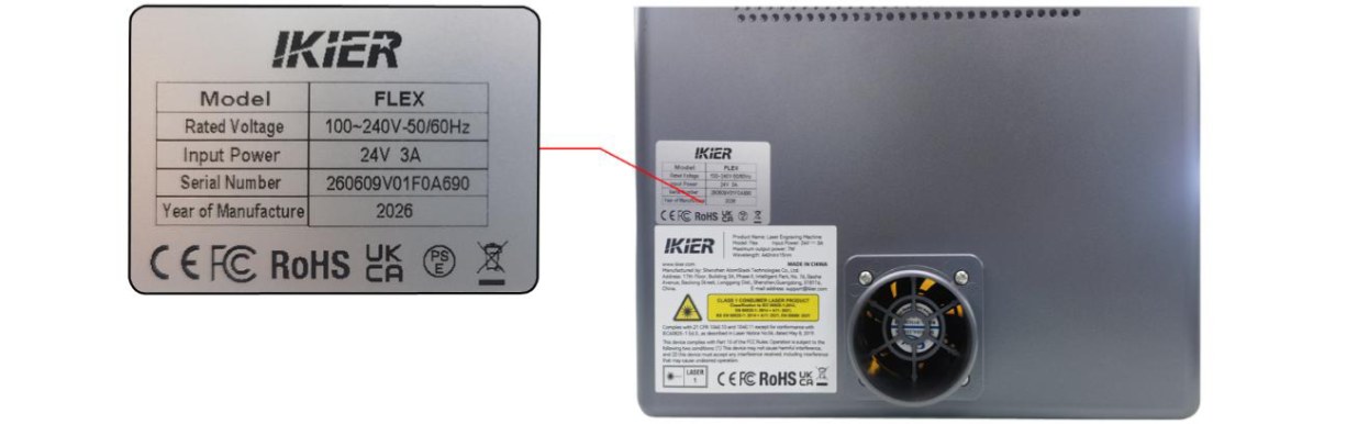
Figure 73
¶ 22. The Red Crosshair Is Not Aligned with the Laser Engraving Position
Follow the steps below to resolve the issue:
- PC Software Operation
① Reset the Device After successfully connecting to the device, first home the machine to ensure that the coordinates are reset to zero. ② Enter the Calibration Interface
- Open“Device Information”in the upper-right corner of the software and confirm that“Red Crosshair
Positioning”is selected under “Positioning Mode”.
- Click the “Calibrate”button to the right of“Red Crosshair Positioning”to enter the crosshair calibration interface. ③ Check the Working Area Click“Frame”to confirm that the calibration pattern is within the engraving area. ④ Engrave the Cross Pattern Click“Engrave”. The machine will engrave a cross pattern as a calibration reference. ⑤ Align the Crosshair with the Cross Pattern Follow the instructions in the pop-up window and use the directional movement buttons to adjust the laser head position until the red crosshair is perfectly aligned with the engraved cross pattern. Tip: If the movement distance is too large for a single adjustment, you can manually adjust the step size (i.e., the distance the laser head moves each time you click a directional button) for more precise control. ⑥ Complete the Calibration Click“Done”. The system will save the calibration results, and the calibration process is complete.
- Mobile App Operation
① Enter the Calibration Interface Open the app's home page, then tap“Settings”in the upper-right corner or in the bottom menu bar to enter the device settings interface. ② Engrave the Cross Pattern Tap“Red Crosshair Positioning”. In the“Mark Current Position”interface that appears, tap the center of the circle. The machine will engrave a cross pattern as a calibration reference. ③ Align the Crosshair with the Cross Pattern After engraving is complete, follow the instructions in the pop-up window and use the directional movement buttons to adjust the laser head position until the red crosshair is perfectly aligned with the engraved cross pattern. Tip: If the movement distance is too large for a single adjustment, you can manually adjust the step size (i.e., the distance the laser head moves each time you click a directional button) for more precise control. ④ Complete the Calibration After confirming that the crosshair is perfectly aligned with the engraved cross pattern, tap“Done”. The system will automatically save the calibration results, and the calibration process is complete.
¶ 23. The Engraving Machine Does Not Hit the Frame During Framing, but Hits the Frame During Engraving
Please follow the steps below to troubleshoot the issue:
- Confirm the Laser Type
-
Diode Laser: Proceed directly to Step (2).
-
Infrared Laser: Since there is a certain offset between the laser emission point and the center point of the crosshair, the laser module will move an additional distance during engraving compared with framing.
- Test with Different Control Software
We recommend using AtomStack Studio or LightBurn. Try using a different software program for engraving and check whether the issue still occurs, in order to rule out software version-related factors.
- Restore Factory Settings
If the issue persists after completing the above steps, restore the machine to its factory settings and eliminate the possibility of incorrect parameters causing the issue.
- Contact Customer Support
If the problem still cannot be resolved, please contact Customer Support and provide the following information:
-
Fault video: Show the software interface, file design, framing process, and the issue that occurs.
-
A description of the troubleshooting steps you have already performed.
-
A photo of the Serial Number label on the back of the machine (see Figure 74).
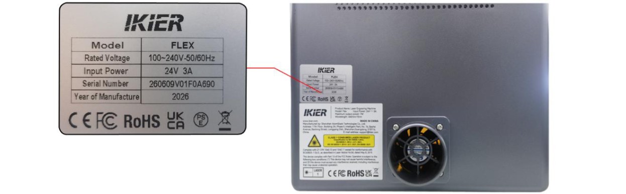
Figure 74
¶ 24. When Using the Infrared Laser, the Framing Position Does Not Match the Engraving Position
Please follow the steps below to troubleshoot the issue:
- Calibrate the Red Crosshair
Refer to the "The Red Crosshair Is Not Aligned with the Laser Engraving Position" section and calibrate the red crosshair accordingly.
- Test with Different Control Software
Make sure you are using the official AtomStack Studio software or a genuine licensed version of LightBurn. If you are currently using LightBurn, try using AtomStack Studio to perform an engraving test and check whether the issue still occurs, in order to rule out software version compatibility issues.
- Restore Factory Settings
If the issue persists after completing the above steps, restore the machine to its factory settings and eliminate the possibility of incorrect parameters causing the issue.
- Contact Customer Support
If the problem still cannot be resolved, please contact Customer Support and provide the following information:
-
Fault video: Show the software interface, file design, framing process, and the issue that occurs.
-
A description of the troubleshooting steps you have already performed.
-
A photo of the Serial Number label on the back of the machine (see Figure 75).
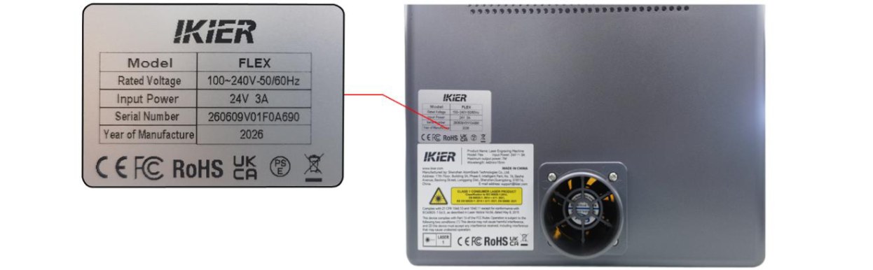
Figure 75
¶ 25. The Machine Hits the Frame During Homing and Displays "Homing Failed"
Please follow the steps below to troubleshoot the issue:
- Check for Foreign Objects Inside the Enclosure
Open the enclosure door and check whether any foreign objects are blocking the laser module's movement path. If any are found, remove them immediately.
- Manually Press the Limit Switches to Test Them
Press the limit switches on both sides of the laser module, as well as the front and rear Y-axis limit switches on the right side, as shown in Figure 76. Check whether the alarm sound (beep) is triggered correctly.
- If the alarm is triggered correctly, the limit switches are functioning properly. Proceed directly to **Step
- **.
- If any switch does not trigger the alarm, check whether its cable connection is loose. If the cable is properly connected but the switch still does not respond, the limit switch may be damaged.
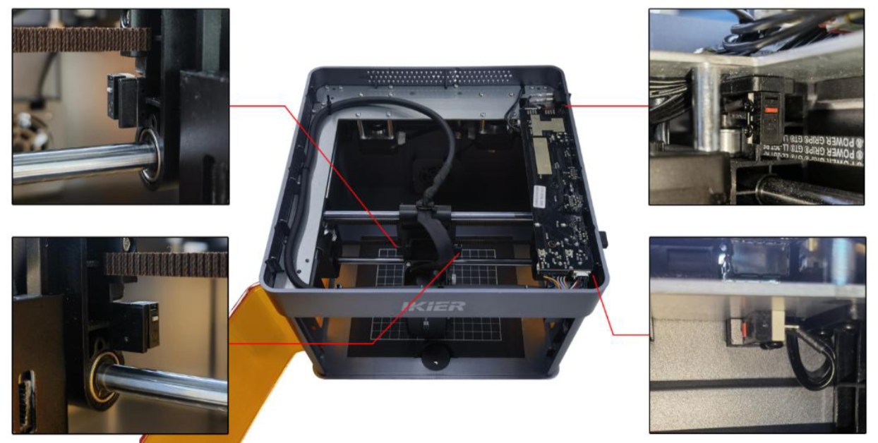
Figure 76
- Check the Limit Switch Cable Connections on the Mainboard
Open the top cover of the machine and check the limit switch cable connections on the mainboard (see Figure 77) for loose connections, broken wires, or poor contact. If any abnormality is found, reconnect or replace the cable as necessary.
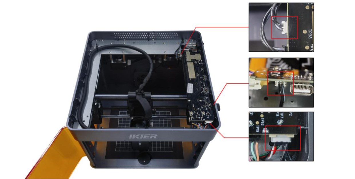
Figure 77
- Restore Factory Settings
If the issue persists after completing the above steps, restore the machine to its factory settings and eliminate the possibility of incorrect parameter settings.
- Contact Customer Support
If the problem still cannot be resolved, please contact Customer Support and provide the following information:
-
Fault video: The video should clearly show the complete homing process and the manual limit switch test.
-
A description of the troubleshooting steps you have already performed.
-
A photo of the Serial Number label on the back of the machine (see Figure 78).
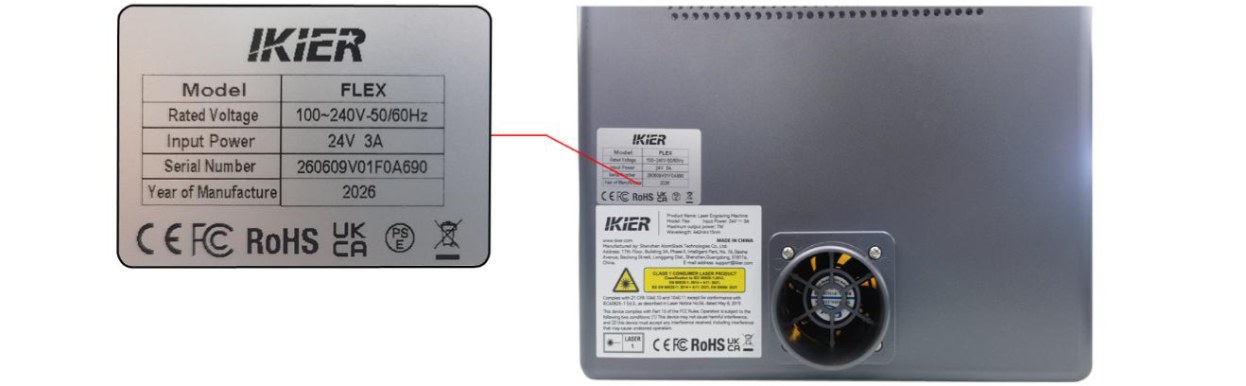
Figure 78
¶ 26. When Processing Thin and Lightweight Materials, the Output Pattern Has "Missing Lines" or the Material Moves
Please follow the steps below to troubleshoot the issue:
- Secure the Four Corners of the Material
The engraving machine comes with 4 small magnets. Use the magnets to secure the four corners of the thin, lightweight material to the base plate to prevent the material from shifting due to airflow from the fan during processing.
- Make Sure the Material Is Lying Flat
Check whether the material is lying flat against the surface of the base plate. If it is warped or wrinkled, flatten it before processing.
- Test with a Different Material
Replace the material with a wooden board or another heavier material. Use the appropriate parameters for the material and perform an engraving test to check whether the output pattern still has "missing lines" or shifts during processing.
- Contact Customer Support
If the problem still cannot be resolved, please contact Customer Support and provide the following information:
-
Fault video: The video should clearly show the complete engraving process and the resulting engraving.
-
A description of the troubleshooting steps you have already performed.
-
A photo of the Serial Number label on the back of the machine (see Figure 79).
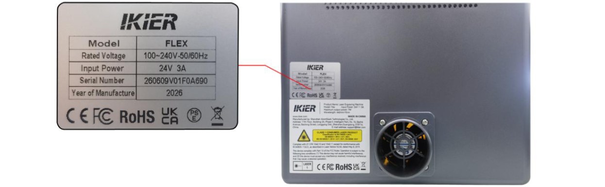
Figure 79
¶ 27. When Engraving Lines, the Output Pattern Is disconnected (Not Closed) at Corners or Junctions
Follow the steps below to troubleshoot the issue:
- Check the Power Settings in the Software
Compare the current settings with the recommended parameter table and check whether they are correct. You can try increasing the power or reducing the speed appropriately and perform a test to see whether the line closure improves.
- Enable Constant Power Mode
Enable “Constant Power”mode in the software and test whether this resolves the issue.
- Adjust the Minimum Power Value
Unclosed lines are usually related to the laser's minimum power value ($31) being set too low. Adjust the value as follows:
- AtomStack Studio:
①Open the “Settings”menu, then left-click the software version number more than 7 times consecutively to activate“Developer Mode”. ② Click“Serial Port Log”in the menu bar to open the console. ③ Enter and send“$31=”in the command input field (where * represents the specific value). Gradually increase the value until the lines are closed. For example, if the lines cannot be closed when“$31”is set to “0”, send “$31=10”. If the lines are still not closed, continue increasing the value and send “$31=20”, and so on until the lines are fully closed.
- LightBurn:
① Click“Edit”, select“Machine Settings”, and locate $31. ② Gradually increase the value, then click“Write”→“OK”to save the settings. ③ Repeat this process, continuously increasing the $31 value until the lines are fully closed.
- Restore Factory Settings
If the issue persists after completing the above steps, restore the machine to its factory settings and eliminate the possibility of incorrect parameters causing the issue.
- Contact Customer Support
If the problem still cannot be resolved, please contact Customer Support and provide the following information:
-
Fault video: Clearly show the software operation steps, engraving process, and engraving results.
-
A description of the troubleshooting steps you have already performed.
-
A photo of the device Serial Number label (see Figure 80).
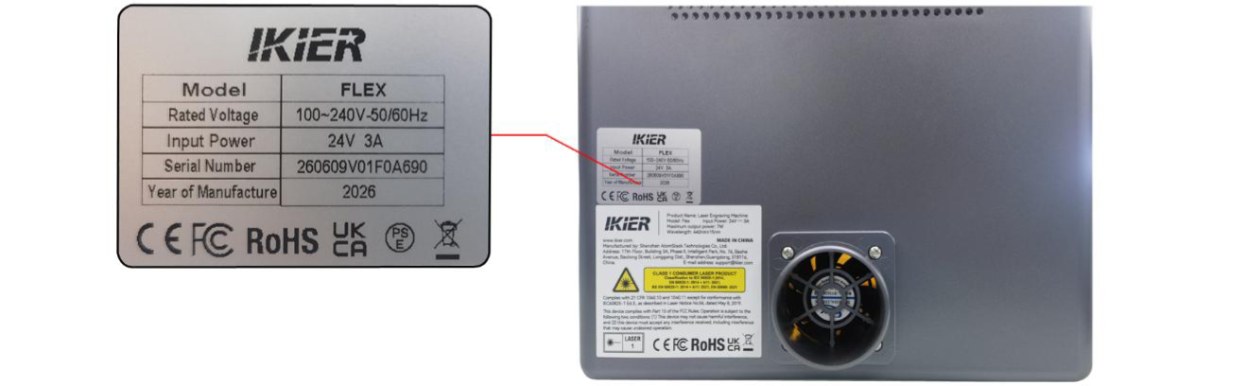
Figure 80
¶ 28. When Engraving Circles or Squares, the Lines at the Corners or Junctions of the Output Pattern Are Disconnected (Not Closed)
Follow the steps below to troubleshoot the issue:
- Check the Power Settings in the Software
Compare the current settings with the recommended parameter table and check whether they are correct. You can try increasing the power or reducing the speed appropriately and perform a test to see whether the line closure improves.
- Enable Constant Power Mode
Enable “Constant Power”mode in the software and test whether this resolves the issue.
- Adjust the Minimum Power Value
Unclosed lines are usually related to the laser's minimum power value ($31) being set too low. Adjust the value as follows:
- AtomStack Studio:
①Open the “Settings”menu, then left-click the software version number more than 7 times consecutively to activate“Developer Mode”. ② Click“Serial Port Log”in the menu bar to open the console. ③ Enter and send“$31=”in the command input field (where * represents the specific value). Gradually increase the value until the lines are closed. For example, if the lines cannot be closed when“$31”is set to “0”, send “$31=10”. If the lines are still not closed, continue increasing the value and send “$31=20”, and so on until the lines are fully closed.
- LightBurn:
① Click“Edit”, select“Machine Settings”, and locate $31. ② Gradually increase the value, then click“Write”→“OK”to save the settings. ③ Repeat this process, continuously increasing the $31 value until the lines are fully closed.
- Restore Factory Settings
If the issue persists after completing the above steps, restore the machine to its factory settings and eliminate the possibility of incorrect parameters causing the issue.
- Contact Customer Support
If the problem still cannot be resolved, please contact Customer Support and provide the following information:
-
Fault video: Clearly show the software operation steps, engraving process, and engraving results.
-
A description of the troubleshooting steps you have already performed.
-
A photo of the device Serial Number label (see Figure 81).
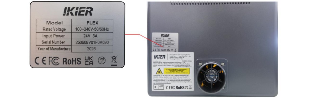
Figure 81
¶ 29. Smoke and Fumes Inside the Enclosure Cannot Be Exhausted in Time
If smoke and fumes are not being properly exhausted, follow the steps below to troubleshoot the issue:
- Check the Enclosure Fan
- Check whether the fan is running
Observe whether the fan operates normally during engraving or cutting. If the fan is not running properly, check whether the fan cable is securely connected to the mainboard. Disconnect the cable and reconnect it to see if the issue is resolved. If the problem persists, use an adapter to supply power to the fan separately to test whether the fan can operate normally.
- Check whether the fan blades are intact
If the fan is running, carefully check whether the fan blades are cracked, broken, or damaged. Broken or damaged fan blades can significantly reduce exhaust performance and cause abnormal noise.
- Check whether the fan has accumulated dust
If the fan blades are intact, check whether there is dust buildup on their surface. If they are dirty, clean them.
- Check the Exhaust Hose
Make sure the exhaust hose is not bent or blocked, and ensure that the exhaust passage is unobstructed.
- Troubleshoot the Air Purifier
If an air purification device (air purifier) is connected, try disconnecting the exhaust hose from the air purifier and directing the exhaust directly outdoors. Check whether the exhaust performance improves:
-
Exhaust returns to normal: This indicates that the issue may be with the air purification device, such as a clogged filter or device malfunction.
-
Exhaust is still abnormal: Continue checking the enclosure fan or exhaust hose.
- Contact Customer Support
If the problem still cannot be resolved after completing the above steps, please contact Customer Support and provide the following information:
-
Fault video: Clearly show the fan status, exhaust hose condition, and exhaust performance.
-
A description of the troubleshooting steps you have already performed.
-
A photo of the device Serial Number label (see Figure 82).
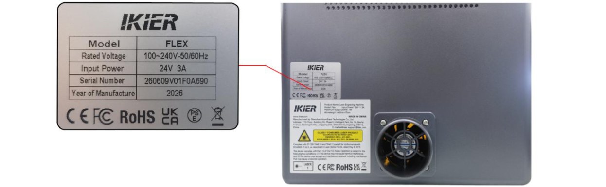
Figure 82
¶ 30. Abnormal Friction Noise During Engraving or Brown Debris Inside the Enclosure
Please follow the steps below to troubleshoot the issue:
- Check the Timing Belt Idler Pulleys
Turn off the engraving machine and open the enclosure door. Check each idler pulley that the timing belt passes through and make sure that the timing belt has not come off the pulley groove.
- Check the Motor Timing Pulley
Turn off the machine, open the enclosure door and the top cover, and check whether the motor timing pulley is properly aligned with the timing belt, with no pulling or angled tension, as shown in Figure 83. If any abnormality is found, loosen the screws on the timing pulley, adjust it to the proper position, and then tighten the screws.
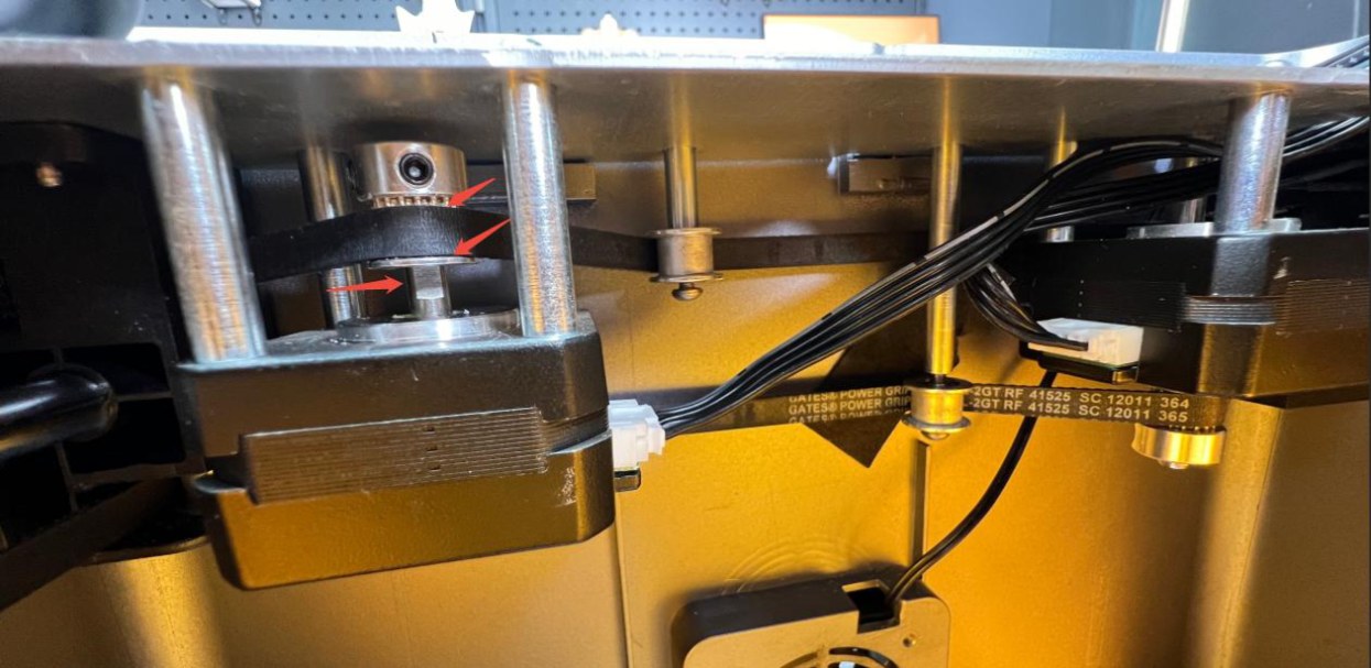
Figure 83
- Check the Surface of the Linear Shafts
Open the top cover and check the surfaces of the three linear shafts for signs of friction or wear. Also check whether the grease is dry or insufficient. If necessary, clean and lubricate them.
- Contact Customer Support
If the problem still cannot be resolved after completing the above steps, or if you have identified an issue that you cannot repair yourself, please contact Customer Support and provide the following information:
-
Fault video: Clearly show the issue and the abnormal condition.
-
A description of the troubleshooting steps you have already performed.
-
Clear photos of the faulty component.
-
A photo of the device Serial Number label (see Figure 84).
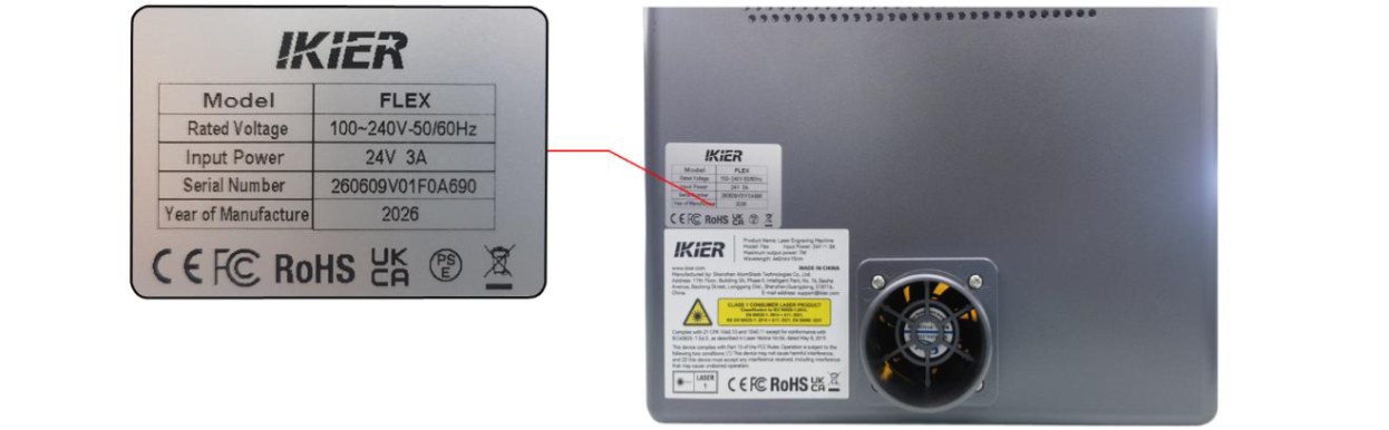
Figure 84
¶ 31. Updating AtomStack Studio, the Engraving Machine Firmware, and the Mobile App
- Updating AtomStack Studio
Open the software and click "Settings" in the upper-left corner to enter the Settings interface. At the bottom of the interface, you can view the current version number and the "Check for Updates" button, as shown in Figure 85.
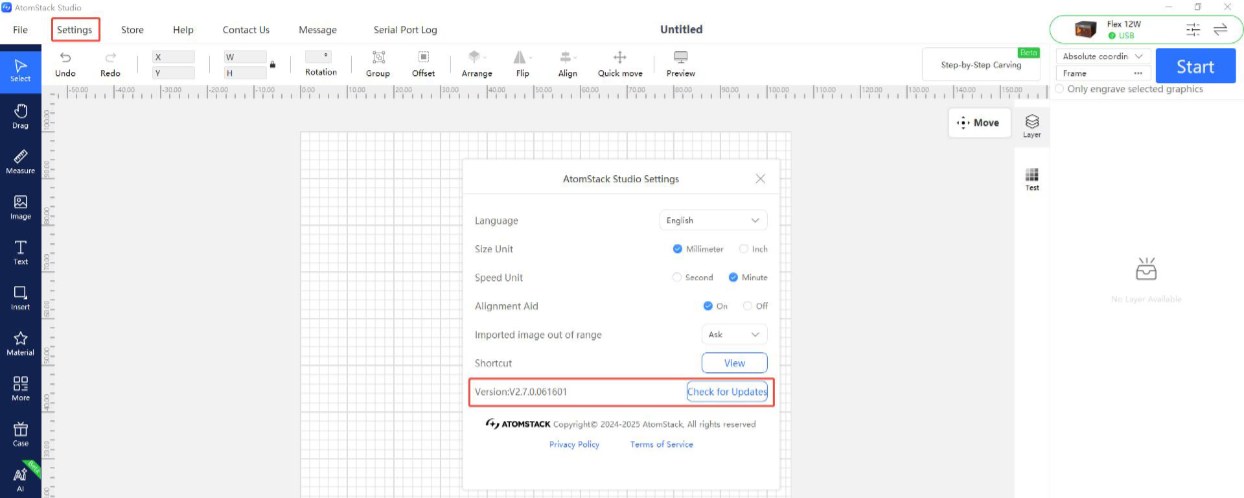
Figure 85
- Updating the Engraving Machine Firmware
-
All firmware update methods require a TF card as the storage medium. Do not turn off the machine or remove the TF card during the update process.
-
Updating the Firmware via AtomStack Studio
Open the software and connect the engraving machine. Click the "☰" icon in the upper-right corner of the software interface to enter the Device Information interface. The current firmware version is displayed at the bottom of the interface. If an update notification appears to the right of the version number, click it to start the update, as shown in Figure 86.
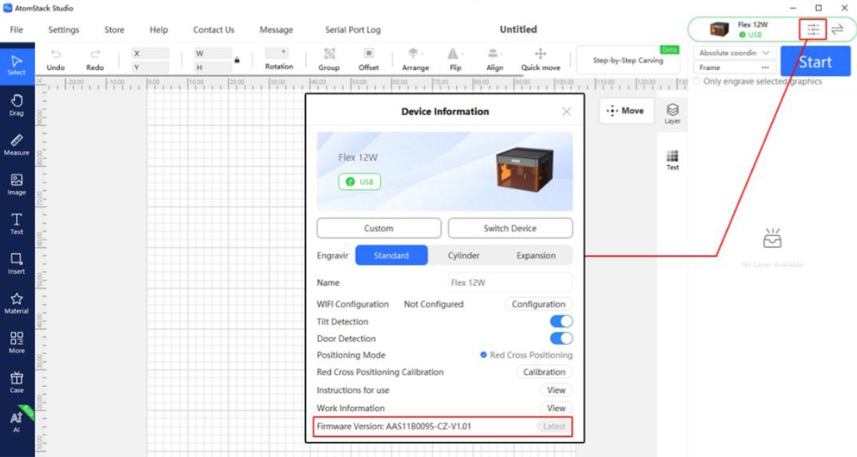
Figure 86
- Updating the Firmware via the AtomStack App
Open the app and connect the engraving machine. Tap "Settings" below the model name to enter the Device Settings interface. At the bottom of the interface, you can view the current firmware version and the option to update to the latest firmware, as shown in Figure 87.
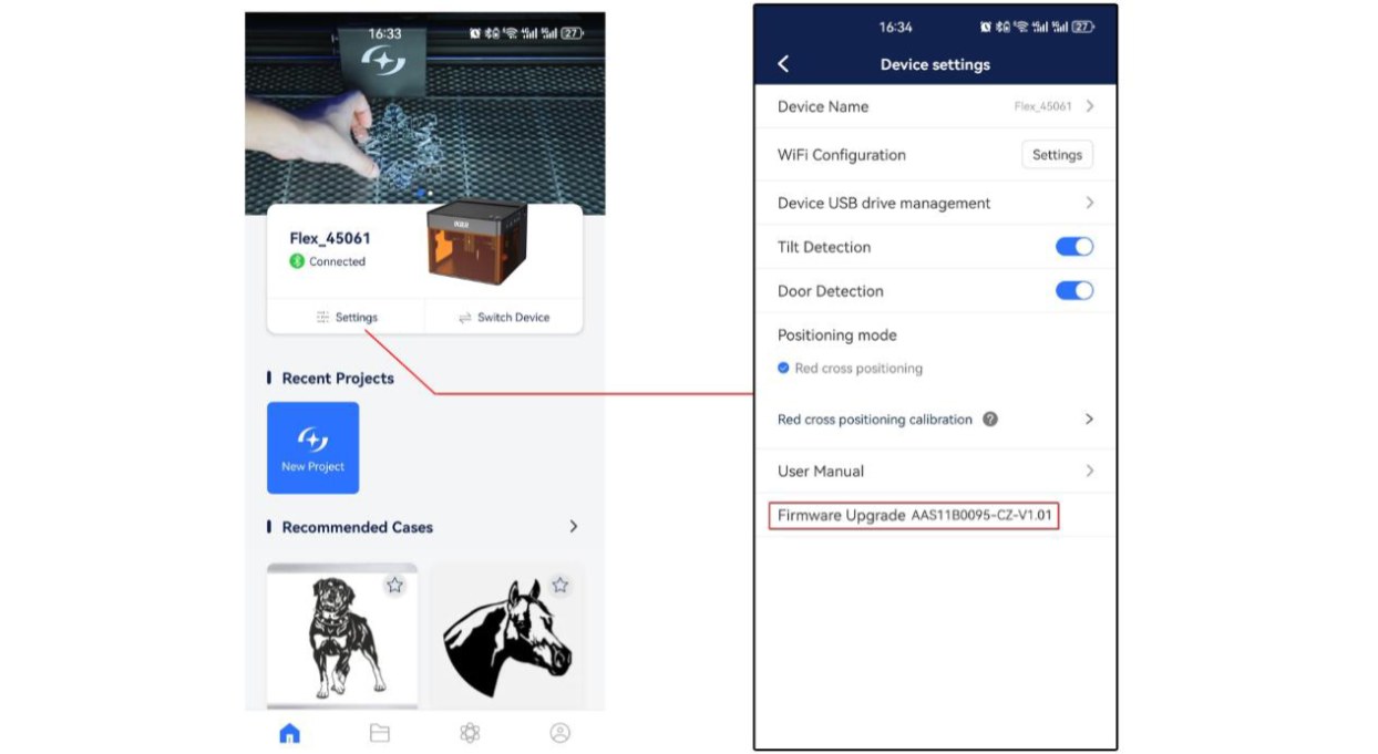
Figure 87
- Updating the Firmware via a TF Card
If the firmware cannot be updated using either of the above methods, provide Customer Support with a screenshot showing the current firmware version of the engraving machine and a photo of the machine's Serial Number label (see Figure 88) to obtain the latest firmware. Then follow the steps below to update the firmware:
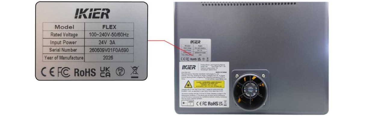
Figure 88
① Remove the TF card, insert it into a card reader, and connect the card reader to a computer. ② Copy the new firmware file (.bin file) to the root directory of the TF card. Do not place the file inside a folder. ③Insert the TF card back into the engraving machine and turn on the machine. The device will automatically start the update and emit a series of beeping sounds. ④ Wait until the beeping stops, then restart the engraving machine.
- Updating the Mobile App
Open the mobile app and tap "Profile" → "Settings" → "About ATOMSTACK" in the lower-right corner of the home page to enter the corresponding interface. You can view the current app version there. If a new version is available, an update option will be displayed. If no update is available, "You're up to date" will be displayed, as shown in Figure 89.
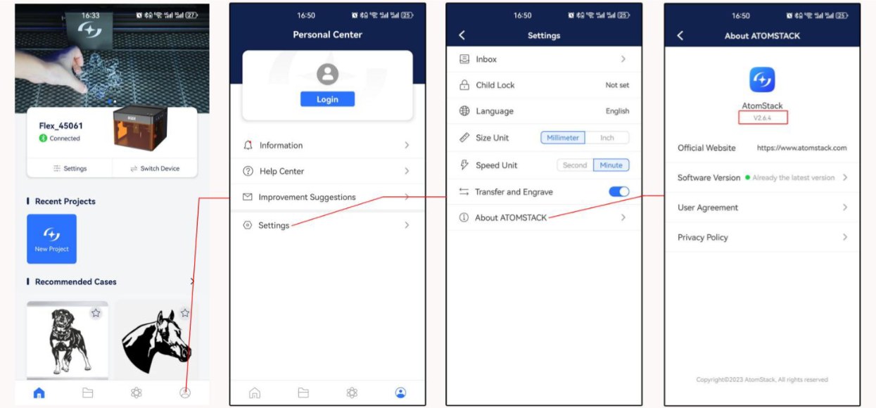
Figure 89
¶ 32. Software Alarm Codes and Troubleshooting
| Alarm Code | Description | Troubleshooting |
|---|---|---|
| Alarm 1 | Limit switch triggered | If an alarm occurs during normal operation without hitting the limit switch, manually press each limit switch to check whether it can be triggered normally and whether an alarm sound (beep) is produced. Alternatively, unplug the cables of the limit switches one by one and check whether the issue can be reproduced, to identify the faulty component. |
| Alarm 2 | Software limit triggered | Check whether the software limit function is enabled. The software limit setting is located in the $20 parameter in the machine settings. If enabled, it needs to be disabled. In the software, go to Edit → Machine Settings to configure the setting. |
| Alarm 3 | Engraving stopped | Refer to the prompts displayed by the software and follow the instructions to troubleshoot the issue. |
| Alarm 8 | Limit switch continuously triggered | The limit switch may be damaged. You can unplug the limit switch cables one by one to identify the faulty component. |
| Alarm 11 | Tilt alarm | Make sure the engraving machine is placed on a level surface. If the alarm persists, open the machine lid and tighten the fixing screws on the sides of the mainboard. |