¶ Flex Machine Operation
Follow these sections for installation, computer or mobile connection, laser module switching, and focusing.
¶ 1. Unboxing and Installation
Note
Check the Accessories: After unboxing, check all accessories against the user manual to ensure that all items are included.
Connect Correctly: During installation, follow the instructions in the user manual to connect each interface and ensure that all connections are correct.
Check the USB Key: The device must have the USB Key inserted to be unlocked and used. Make sure that the USB Key is properly inserted.
¶ 2. Control Panel Overview
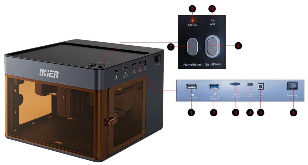
- USB Key (USB Key Port)
Insert the USB Key to unlock the machine. If the USB Key is not inserted, the device will remain in an alarm state and cannot be used.
- Accessory Interface
Used to connect R6, R8, and R8 PRO rotary devices.Note: Due to the non-removable base plate, this model does not support rotary devices.
- TF Card (TF Card Slot)
A storage capacity of 4 GB or 8 GB is recommended. It is recommended not to use a TF card larger than 16 GB.
- Computer (Type-C Data Port)
Connect the machine to a computer using a Type-C data cable.
- Input (Power Input)
Input rating: 24 V / 3 A.
- Emergency (Power Switch)
Controls the power on/off of the engraving machine.
- Frame/Repeat
Available only when the machine is controlled through the app.
-
Short press: Start/stop framing.
-
Press and hold for more than 3 seconds: Repeat the previous processing task.
- Start/Pause
-
Short press: Pause/resume the current task.
-
Double-click: Clear the error status.
-
Press and hold for more than 3 seconds: Enter Wi-Fi pairing mode.
-
Green button halo: Indicates that an accessory, such as the R6 Roller or R8 Chuck, is connected.
- Status (Status Indicator)
-
Solid green: The machine is powered on normally and in standby mode.
-
Flashing green: The current task is paused.
-
Solid red: Fault alarm.
-
Solid blue: The laser is emitting.
- Wi-Fi (Wireless Connection Indicator)
-
Off: Not connected to a wireless network.
-
Flashing: Connecting to a Wi-Fi network.
-
Solid green: Successfully connected to a wireless network.
¶ 3. Connecting to a Computer
Operating Steps:
- Connect the Device
Use a Type-C data cable to connect the machine's "Computer" port.
- Install the Serial Port Driver
The serial port driver must be installed before using the machine for the first time. Download the driver from the links below:
-
Windows Driver Download: Download Windows Driver
-
macOS Driver Download: Download macOS Driver After installation is complete, open Device Manager and check whether a "CH340" serial port appears (as shown in Figure 1). If it appears, the driver has been installed successfully.
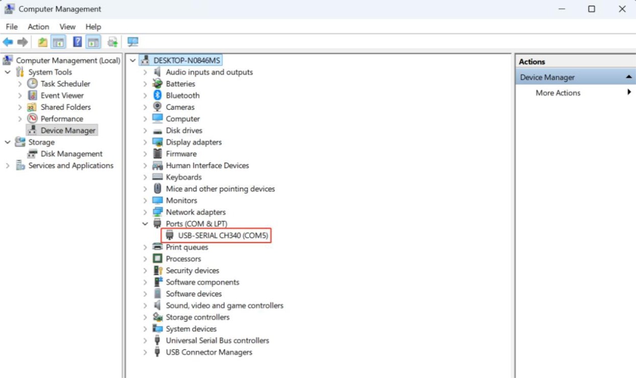
Figure 1
- Install the Control Software
AtomStack Studio or LightBurn is recommended.
-
AtomStack Studio Download: Download AtomStack Studio
-
LightBurn Download: Download LightBurn
- Software Setup Instructions
① AtomStack Studio: The software automatically detects the machine model, so no additional configuration is required.
② LightBurn: Import the Flex configuration file or manually modify the parameters.
-
Manually add the "GRBL" controller.
-
Set the baud rate to 460800, as shown in Figure 2.
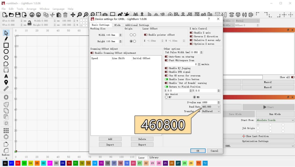
Figure 2
- Set the engraving area as follows:
Blue Diode Laser: 110 mm × 110 mm Infrared Laser: 105 mm × 100 mm
-
Computer System Compatibility Notes
-
Windows: The machine can be connected directly using a Type-C to USB-A cable or a USB-C to USB-C cable.
-
macOS / HarmonyOS: Use a hub or docking station (as shown in Figure 3) and connect the machine through the USB-A port. A direct USB-C connection is not supported.
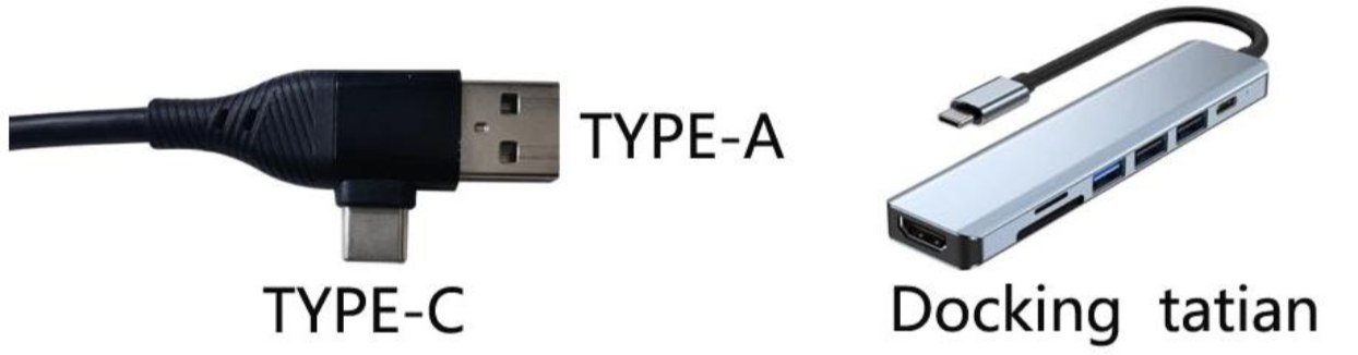
Figure 3
¶ 4. Connecting to the Mobile App
Flex supports three app connection modes: Bluetooth, Wi-Fi, and IP. Bluetooth mode is recommended as the preferred option because it is easier to set up and use.
- Connection Methods
- Bluetooth Mode (Recommended)
Open the app and select Bluetooth Mode. The app will search for the machine and guide you through the network setup and connection process.
- Wi-Fi Mode
Press and hold the “Start/Pause” button on the machine for more than 3 seconds until the Wi-Fi indicator starts flashing white. You can then search for and connect to the machine through the Wi-Fi module in the app.
- IP Mode
First, use Wi-Fi Mode to configure the machine and connect it to the local network. After the machine is connected to Wi-Fi, you can find its IP address under “Home → Device Settings → Wi-Fi Configuration”. Enter the IP address on the IP connection page to establish a connection. For more information, refer to "Connection Help" in the app interface, as shown in Figure 4.
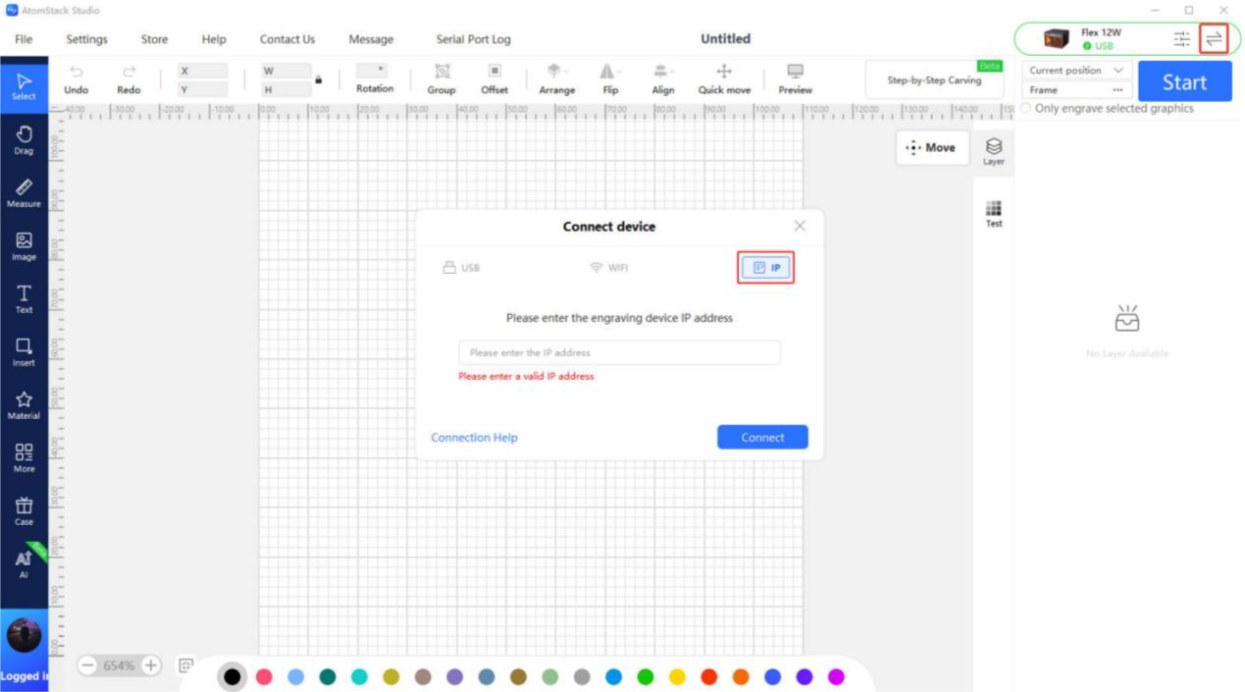
Figure 4
- Requirements for Use
-
A TF card must be inserted before using the mobile app to control the machine for processing.
-
A TF card with a capacity of 4 GB or 8 GB is recommended. It is recommended not to use a TF card larger than 16 GB to ensure normal data reading and writing.
-
For first-time use, it is recommended to connect through Bluetooth Mode first. This method is simple to operate and does not require any additional network configuration.
¶ 5. Switching Between Infrared and Blue Diode Lasers
- Removal
- Turn Off the Power
Before replacing the laser module, always turn off the engraving machine to ensure safe operation.
- Remove the Laser Module
Loosen the knurled screw securing the laser module, remove the laser module, and disconnect the laser module cable.
- Installation
- Loosen the Knurled Screw
Before installing the laser module, loosen the knurled screw to prevent it from obstructing the laser head as it slides into the slider.
- Install and Secure the Laser Module
After installing the laser module into position, adjust the knurled screw and tighten it securely.
¶ 6. Laser Focusing Instructions
Operating Steps:
- Place and Secure the Material
Place the material flat on the work surface. For lightweight materials (such as paper or thin wood boards), it is recommended to use magnets to secure all four corners to prevent the material from moving.
- Loosen the Laser and Swing Down the Focusing Rod
Loosen the knurled screw to allow the laser to slide up and down. Then swing down the focusing rod on the side of the laser. Adjust the laser height until the bottom end of the focusing rod gently touches the surface of the material, as shown in Figure 5.
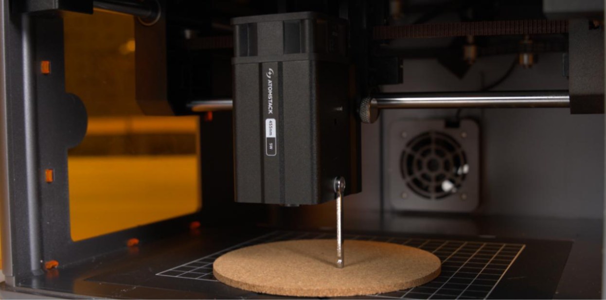
Figure 5
- Secure the Laser and Retract the Focusing Rod
Tighten the knurled screw to secure the laser at the adjusted height. Finally, retract the focusing rod to its original position. The focusing process is now complete.
-
Notes:
-
When tightening the knurled screw, do not apply excessive force. Tighten it only enough to securely hold the laser in place. Over-tightening may damage the threads or slider.
-
When swinging down the focusing rod, gently touch it against the surface of the material. Do not press down on it, as this may deform the material or cause the focusing rod to shift.
¶ 7. IR Laser Crosshair Calibration
Follow the steps below.
- PC Software Operation
① Reset the Device: After successfully connecting to the device, first home the machine to ensure that the coordinates are reset to zero.
② Enter the Calibration Interface
-
Open “Device Information” in the upper-right corner of the software and confirm that “Red Crosshair Positioning” is selected under “Positioning Mode”.
-
Click the “Calibrate” button to the right of “Red Crosshair Positioning” to enter the crosshair calibration interface. as shown in Figure 6.
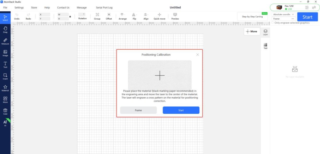
Figure 6
③ Check the Working Area: Click “Frame” to confirm that the calibration pattern is within the engraving area.
④ Engrave the Cross Pattern: Click “Engrave”. The machine will engrave a cross pattern as a calibration reference.
⑤ Align the Crosshair with the Cross Pattern: Follow the instructions in the pop-up window and use the directional movement buttons to adjust the laser head position until the red crosshair is perfectly aligned with the engraved cross pattern. Tip: If the movement distance is too large for a single adjustment, you can manually adjust the step size (i.e., the distance the laser head moves each time you click a directional button) for more precise control.
⑥ Complete the Calibration: Click “Done”. The system will save the calibration results, and the calibration process is complete.
- Mobile App Operation
① Enter the Calibration Interface
- Open the app's home page, then tap “Settings” in the upper-right corner or in the bottom menu bar to enter the device settings interface.
② Engrave the Cross Pattern
- Tap “Red Crosshair Positioning”. In the “Mark Current Position” interface that appears, tap the center of the circle. The machine will engrave a cross pattern as a calibration reference.
③ Align the Crosshair with the Cross Pattern
- After engraving is complete, follow the instructions in the pop-up window and use the directional movement buttons to adjust the laser head position until the red crosshair is perfectly aligned with the engraved cross pattern. Tip: If the movement distance is too large for a single adjustment, you can manually adjust the step size (i.e., the distance the laser head moves each time you click a directional button) for more precise control.
④ Complete the Calibration: After confirming that the crosshair is perfectly aligned with the engraved cross pattern, tap “Done”. The system will automatically save the calibration results, and the calibration process is complete.
¶ 8. AtomStack Studio User Manual
Visit https://install.atomstack.com:6769/ or open “Help”-“Help Center” in the AtomStack Studio software to view and download the user manual.
¶ 9. Brief Introduction to the Software Coordinate Systems
Current Position: The laser's current position is used as the starting point for engraving. You can manually move the laser to any desired engraving position. User Origin: The user manually sets the position where the laser starts working. Absolute Coordinates: The 0,0 coordinate set when the machine is homed is used as the starting point, and the position of the processing object is used as the position where the laser starts working. See Figure 7 for LightBurn and Figure 8 for AtomStack Studio.
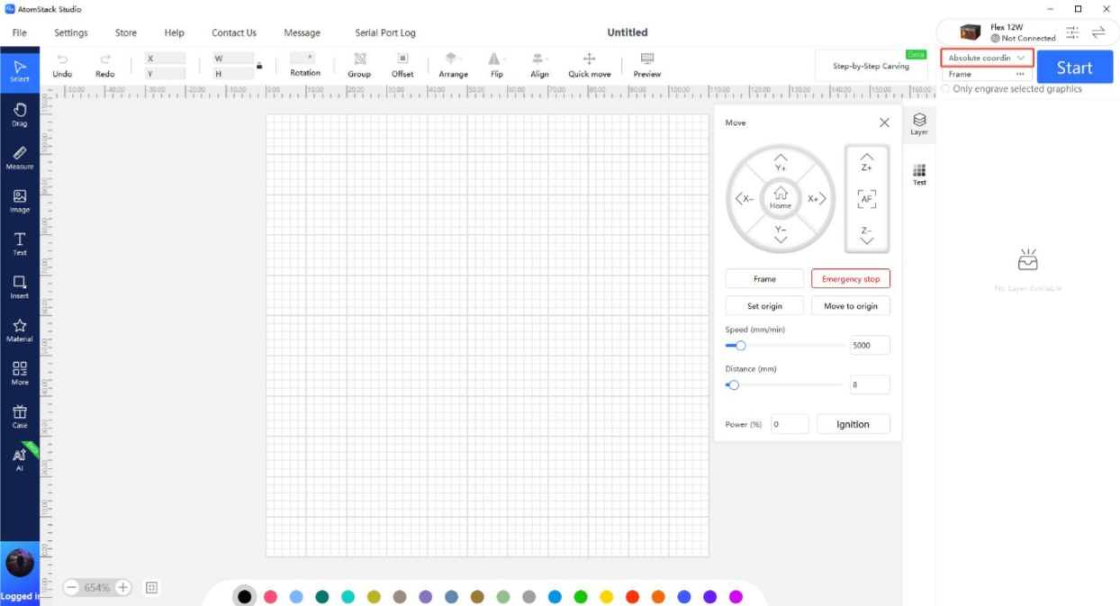
Figure 7
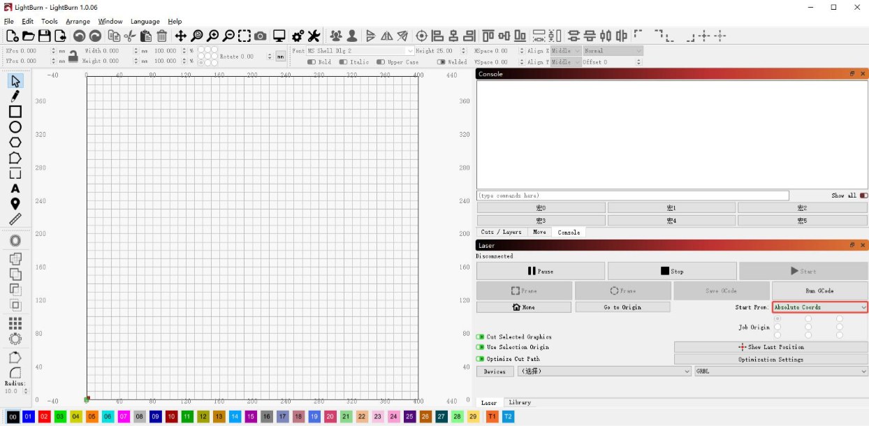
Figure 8