¶ Camera of Master Cannot Be Used
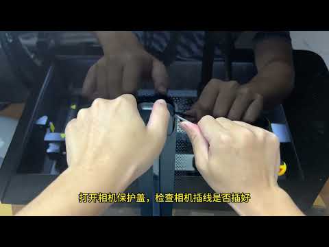
Solution: Please refer to the Master camera troubleshooting video.
- Check the coordinate mode selected in the software:
When using the camera, Absolute Coordinates mode must be enabled.
- Check whether the camera is disabled:
Open Device Manager and check whether the camera has been restricted or disabled. Make sure the necessary permissions are enabled and access is allowed (see Figure 31).
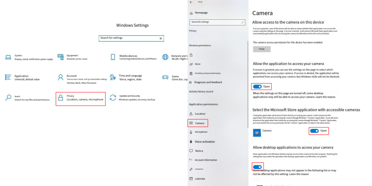
Figure 31
- Check whether the computer USB port is faulty:
Try connecting to a different USB port on the computer, and use the computer’s built-in camera application to check whether the camera outputs an image (see Figure 32).
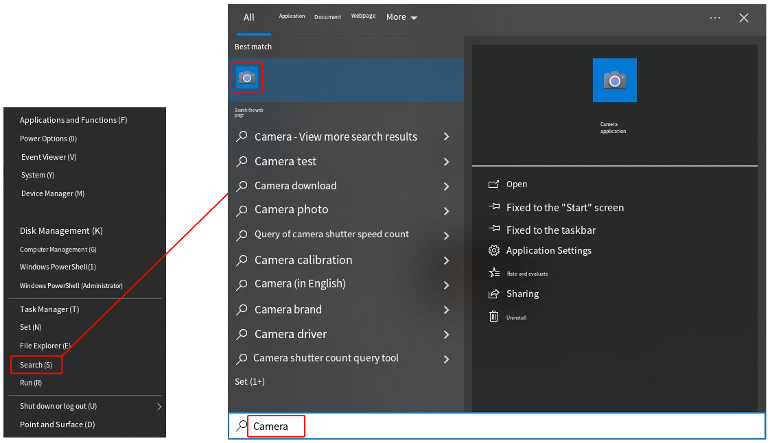
Figure 32
- Check whether the camera USB cable on the mainboard is loose:
If no image is displayed, check whether the camera USB cable connected to the mainboard is loose (see Figure 33). Disconnect and reconnect the cable, then test the camera function again.
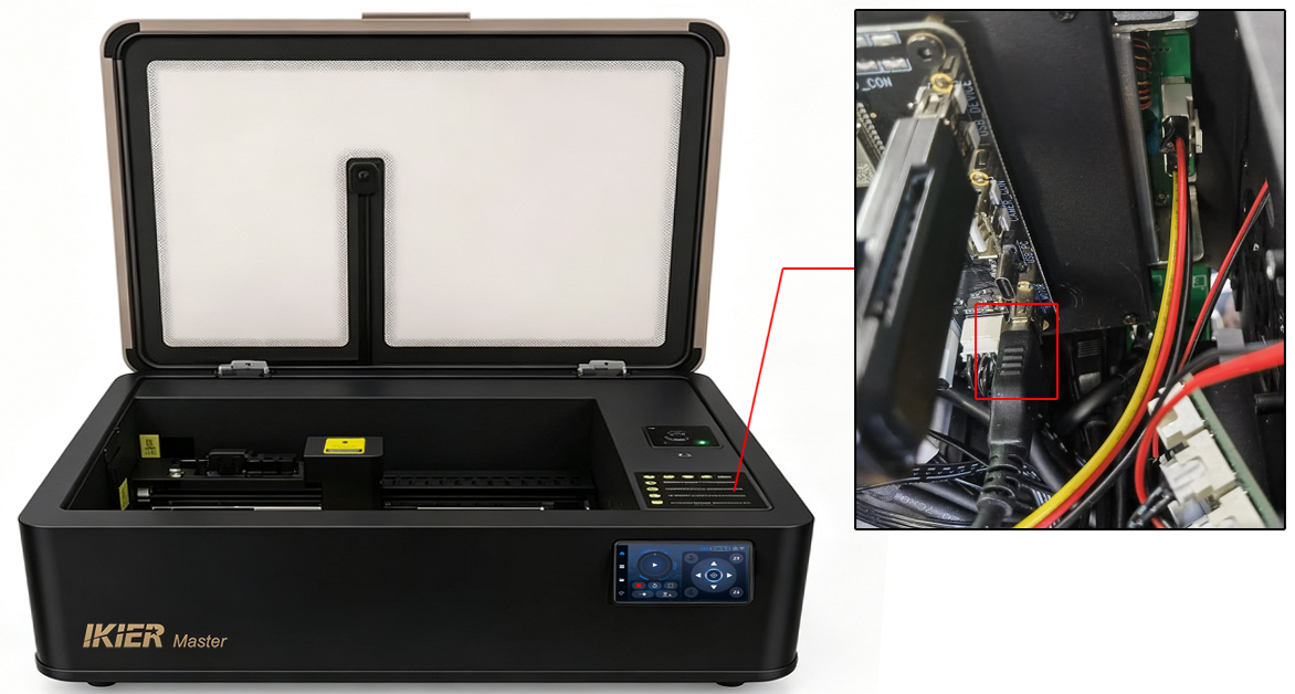
Figure 33
- Check whether the camera cable connection is loose:
Use a flat-head screwdriver to pry open the camera protective cover (see Figure 34), then check whether the cable connector is loose.
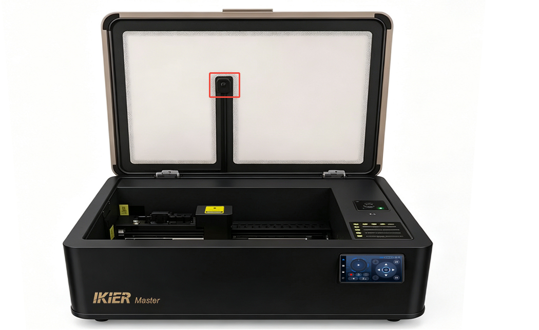
Figure 34
- If the above steps do not resolve the issue and the computer’s built-in camera application still cannot display an image, please send a video showing the issue, the troubleshooting steps already performed, and the machine’s Serial Number (see Figure 35) to customer service for assistance.

For camera replacement instructions, please refer to the Master camera replacement video.
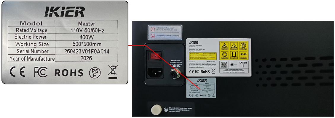
Figure 35
¶ Master’s Camera Positioning Is Inaccurate or Has Large Errors
- Check the coordinate mode selected in the software:
When using the camera, Absolute Coordinates mode must be enabled.
- Confirm that calibration has been completed:
- When using AtomStack Studio, only alignment is required.

- When using LightBurn, follow the instructions in the manual and complete the calibration step by step according to the software prompts. Please refer to the Master camera operation video for calibration guidance.
Note: LightBurn version 1.7.03 or later is recommended, as it provides easier operation and higher calibration accuracy.
- Make sure the interior lighting is bright enough:
The enclosure lighting brightness can be adjusted from the control screen. When using the camera, set the lighting brightness to the maximum level (see Figure 36).
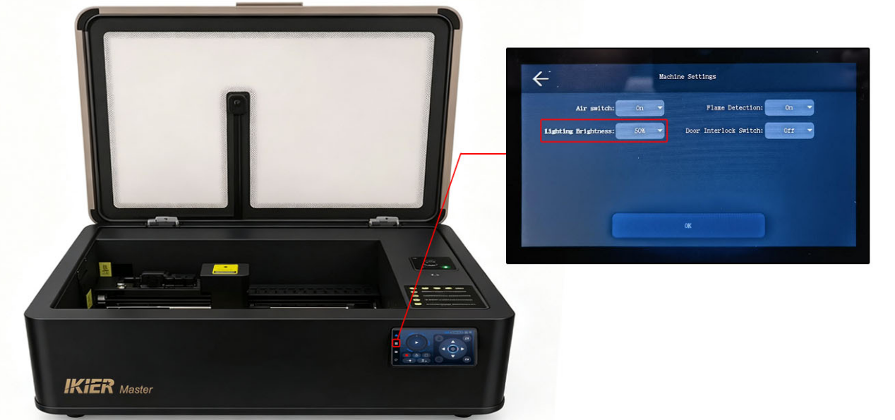
Figure 36
- Make sure the air pump is turned off:
During camera calibration, disable the air assist/air pump function from the control screen (see Figure 37).
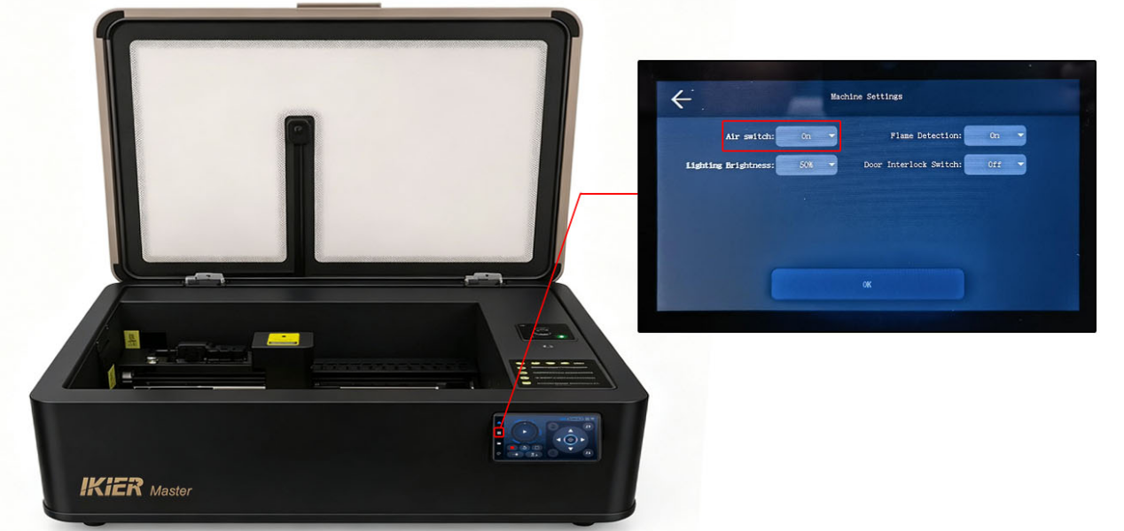
Figure 37
- Check the material height:
The height used during calibration should match, or be very close to, the height of the actual engraving material. If the material height differs significantly from the calibration height, recalibration is required.
- Check the calibration tool:
Kraft paper is recommended for alignment, although plywood may also be used. The calibration piece should be flat and have clear, easily distinguishable lines.
- Confirm operational details:
If lightweight pieces such as kraft paper are used during calibration, make sure they are securely fixed in place to prevent movement during engraving.
¶ After Using the Rotary Attachment with Master, the Engraved Output Appears Mirrored

Solution: Please refer to the troubleshooting guide for mirrored engraving output when using the rotary attachment with Master.
- Check whether mirror mode is enabled:
In the rotary settings of AtomStack Studio or LightBurn, check whether the “Mirror Output” option is enabled (see Figure 79 and Figure 80).
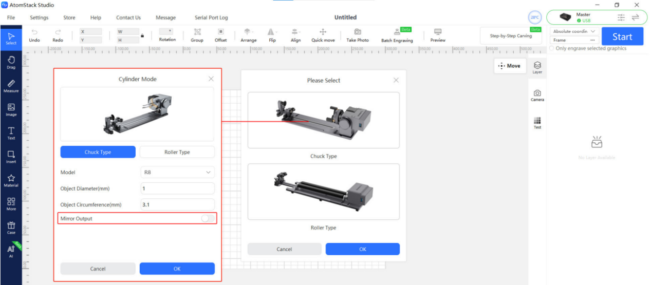
Figure 79
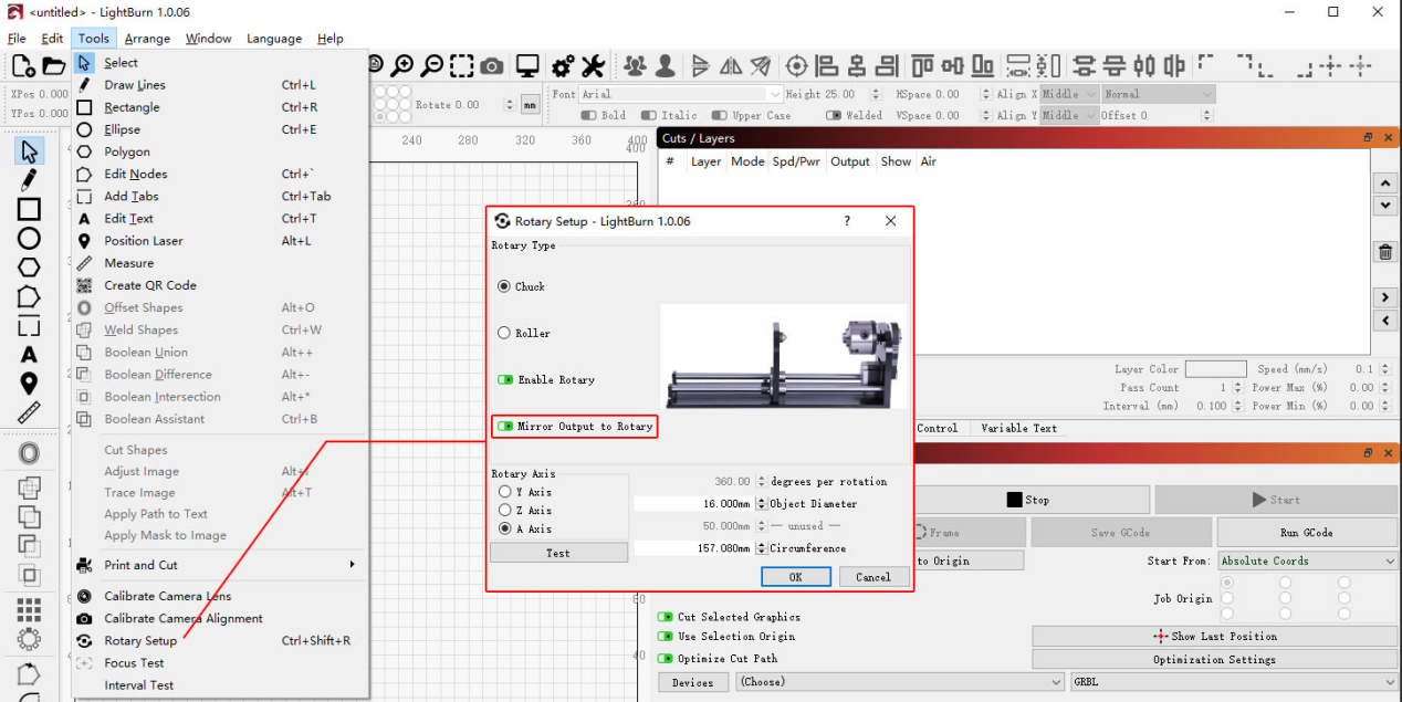
Figure 80
- Check the rotary attachment orientation:
The motor side of the rotary attachment must face the right side.
- Check the A-axis reverse direction setting:
In LightBurn or LaserGRBL:
-
Open the Edit menu
-
Select Machine Settings
-
Find “A Direction Pin Invert ($3)”
If the setting is currently True, change it to False.
If it is currently False, change it to True.
Then click Write, followed by OK to save the settings (see Figure 81).
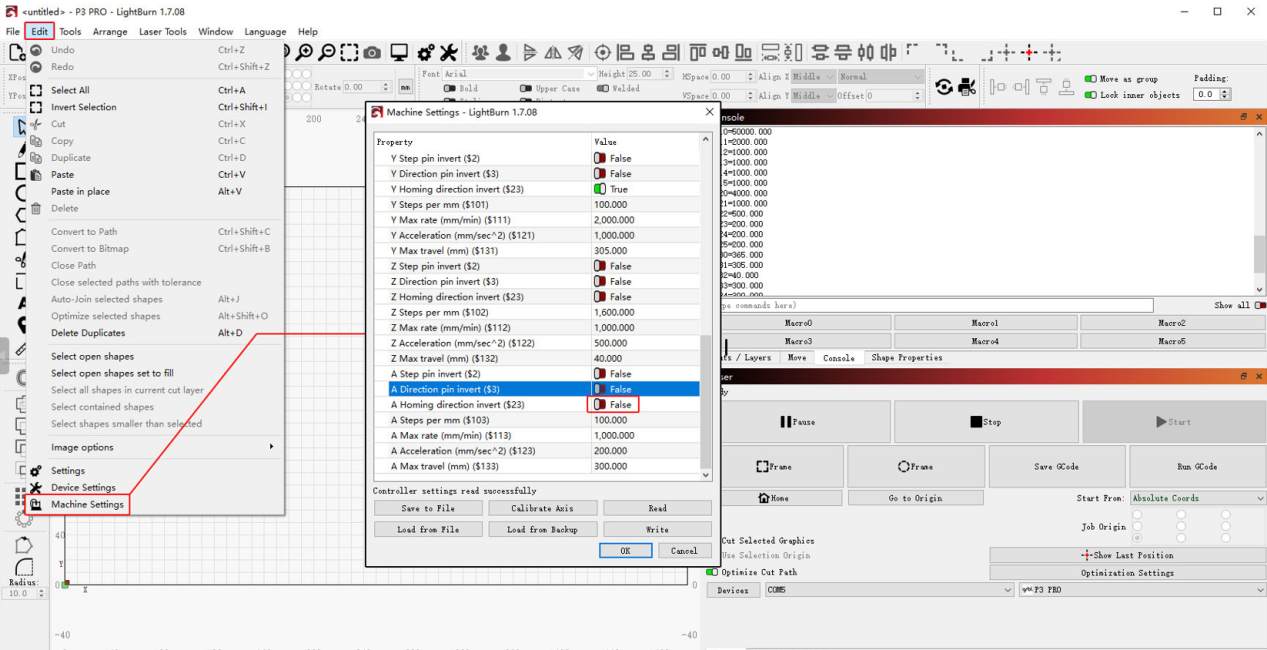
Figure 81
¶ After Using the Rotary Attachment with Master, the Engraved Output Appears Distorted
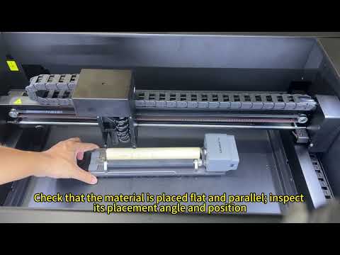
Solution: Please refer to the troubleshooting guide for distorted engraving output when using the rotary attachment with Master.
- Check the software parameter settings:
Verify that the rotary attachment parameters in the control software are set correctly.
Please refer to the “Master Rotary Attachment Usage” section for the correct settings.
- Check the placement of the rotary attachment:
Make sure the rotary attachment is positioned parallel to the X-axis.
- Check the rotary attachment operating condition:
Carefully observe whether the material rotates abnormally while the rotary attachment is operating.
Also check whether there is oil or residue on the material surface that could reduce friction and cause slipping.
Note
If using the R8 chuck rotary attachment, make sure the engraving surface is level after the material is clamped.
¶ Master Cannot Detect the Rotary Attachment
- Check the USB cable connection:
The rotary attachment must be connected using the supplied USB cable (see Figure 82).
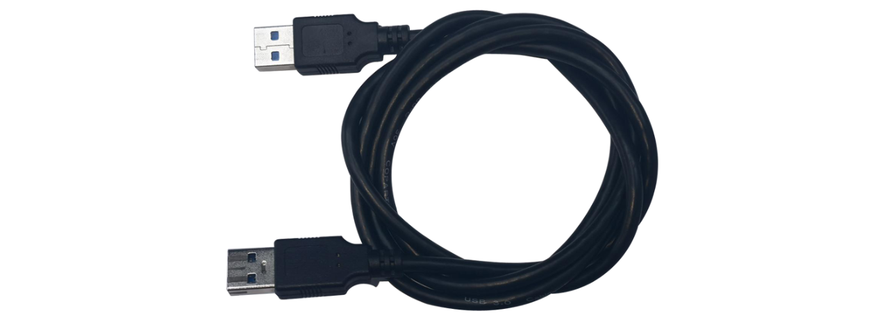
Figure 82
- Check the USB connector on the mainboard:
Open the internal shield panel and check whether the USB connector on the mainboard is loose.
- If the above steps do not resolve the issue, try replacing the rotary auto-detection board and the expansion interface adapter board.
For replacement instructions, please refer to:
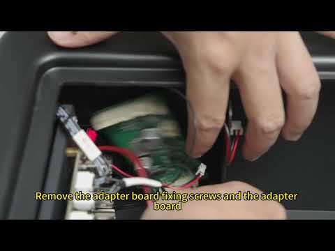
- the Master expansion interface adapter board replacement video