¶ The Master CO₂ Laser Power Is Abnormal and Cannot Fully Cut Through Materials

Solution: Please refer to the Master laser power troubleshooting video.
- Check the reflective mirrors:
With the machine powered off, remove and inspect Mirrors #1, #2, and #3 to check whether they are clean (see Figure 38). If they are dirty, clean them using anhydrous ethanol and a lint-free cloth. Please refer to the “Master Reflective Mirror Cleaning” section for cleaning instructions.
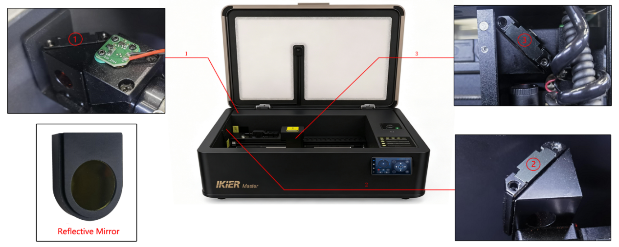
Figure 38
- Check whether the red guide laser dot overlaps with the laser burn spot:
Attach a piece of masking tape or white paper to the focusing lens frame. Press the Laser Test button on the control screen or in the software to briefly fire the laser, then check whether the burn mark overlaps with the red guide laser dot.
If they do not overlap, open the internal shield panel and adjust the beam combiner module screws located in front of the CO₂ laser tube (see Figure 39) until the red guide dot and burn mark align.
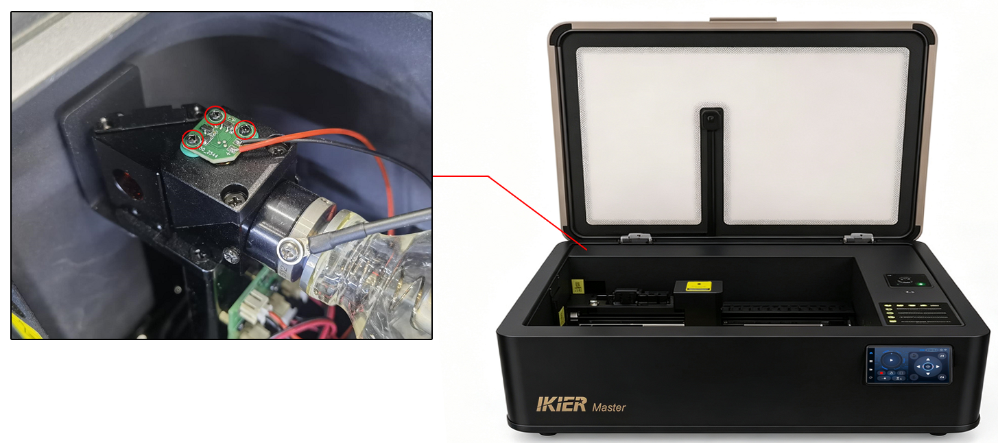
Figure 39
- Check the red guide laser position in the optical path:
With the machine powered on, attach a piece of masking tape or white paper to the third mirror (Z-axis mirror) and mark the current red guide laser position with a pen.
Then move the X-axis and Y-axis around the four inner edges of the enclosure and check whether the red guide laser position shifts relative to the marked point.

If the position shifts, the optical path must be realigned. Please refer to the Master optical path verification and calibration video.
- Check the cutting performance:
Cut a large square-shaped piece of material and check whether all sides are fully cut through.
If one side cuts through properly while another side does not, the optical path needs to be realigned.
- Check the focusing lens:
Remove the cover of the focusing lens tube and take out the focusing lens(see Figure 40). Check whether the focusing lens is damaged.
If it is only dirty, please refer to the “Master Focusing Lens Cleaning” section for cleaning instructions.
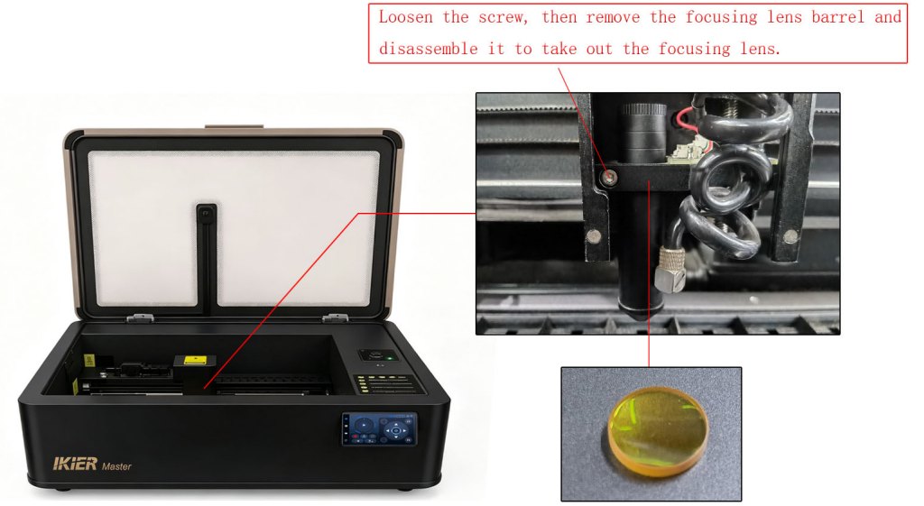
Figure 40
- If no issues are found after completing the above checks, please send the following information to customer service for assistance:
-
A video showing the optical path verification process
-
A cutting test video (clearly showing the software power settings, material type, and material thickness)
-
A photo of the machine’s Serial Number (see Figure 41)

For laser tube replacement instructions, please refer to the Master laser tube replacement video.
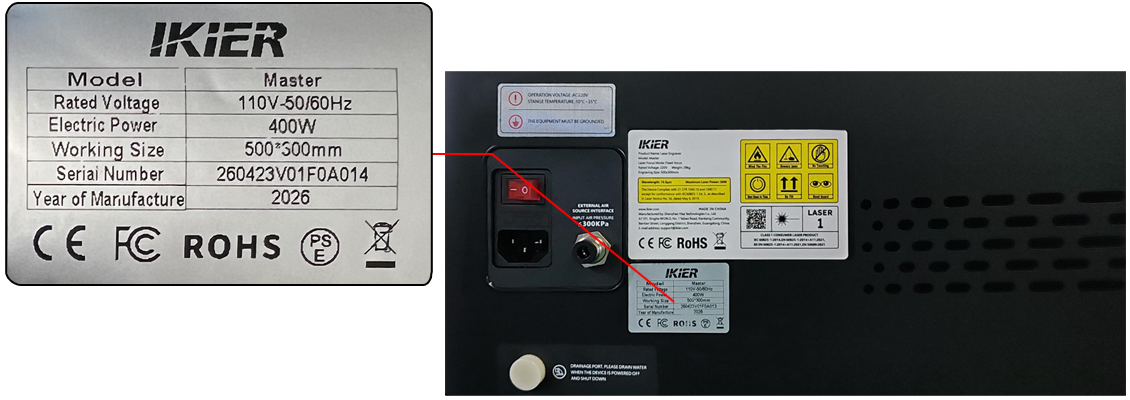
Figure 41
¶ The Master Engraving Output Is Blurry
- Check the focus distance:
The auto focus distance is 8 mm. Please confirm that the distance between the bottom of the Z-axis focusing lens tube and the material surface is 8 mm.
- Check the lenses and mirrors:
After powering off the machine, inspect Mirrors #1, #2, #3, and the focusing lens for dirt or contamination (see Figure 42). If necessary, please refer to the “Master Reflective Mirror Cleaning” and “Master Focusing Lens Cleaning” sections for cleaning instructions.
Figure 42
- Check whether the material has shifted:
If the engraving material is thin or lightweight, secure it properly to prevent movement during the engraving process.
¶ The Master Engraving Output Has Ghosting or Double Images
- Check the timing belts:
Press the X-axis and Y-axis timing belts by hand to check whether they are too loose or too tight. If adjustment is needed, use the belt tensioners located on the right side of the X-axis and the inner side of the Y-axis to adjust the belt tension (see Figure 43).
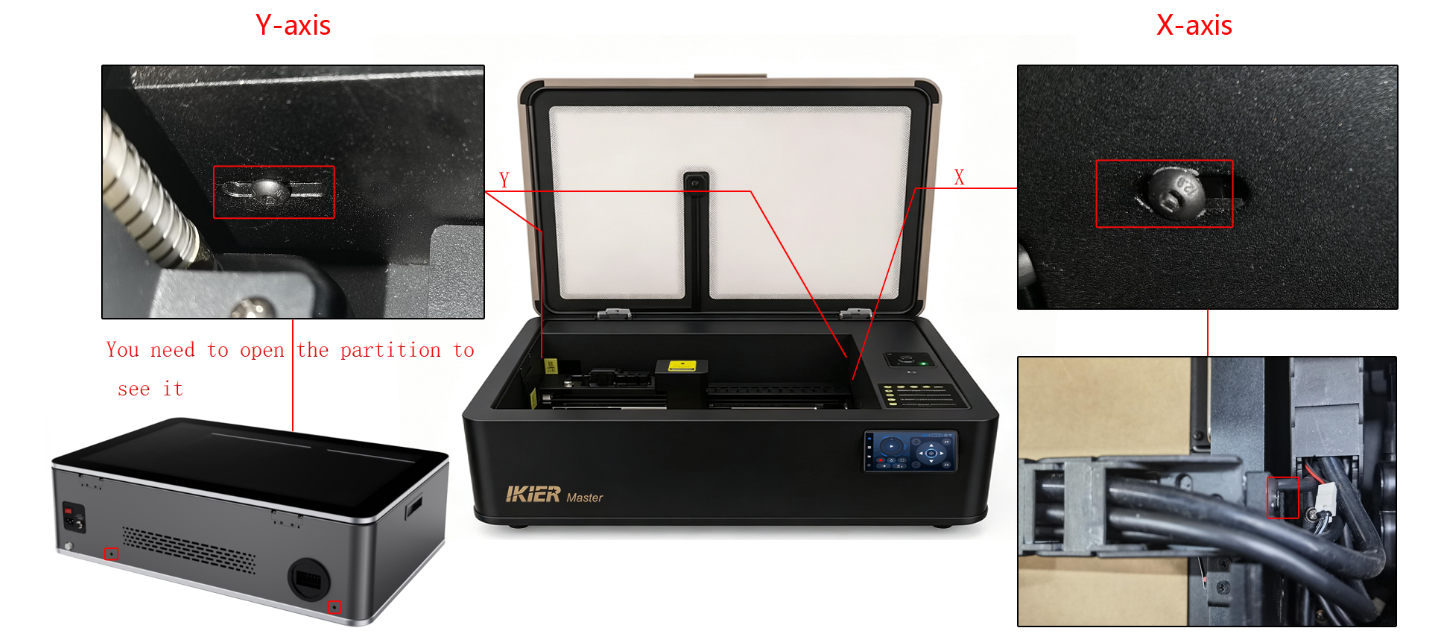
Figure 43
- Check the X/Y timing pulley screws:

To inspect the timing pulley screws, the outer cover and the X-axis motor mounting screws must first be removed. Please refer to the Master structural adjustment video.
- Check whether the X-axis is parallel to the upper and lower frame edges:
Use a ruler to measure whether the distances from both ends of the X-axis to the lower enclosure frame are equal.
If the distances are inconsistent, adjustment is required. Loosen the coupling screws on the Y-axis motor to make the adjustment. Please refer to the structural adjustment video.
- Check the software parameters:
Verify whether the engraving speed set in the software is too high. Please refer to the recommended parameter table. The speed unit is mm/min.
- Check whether the material has shifted:
If the engraving material is thin or lightweight, secure it properly to prevent movement during the engraving process.
¶ The Machine Moves During Engraving, but the Laser Tube Does Not Emit Laser

Solution: Please refer to the Master laser tube no-output troubleshooting guide.
- Check the laser power supply:
Turn off the machine power, open the internal shield panel, then power the machine back on and check whether the indicator light on the laser power supply (located on the right side near the laser tube) lights up normally.
If the indicator light does not turn on, the laser power supply may be faulty. Please send a video showing the issue and the machine’s Serial Number to customer service for assistance.

If replacement is required, please refer to the Master laser power supply replacement video.
- Check the laser power supply wiring:
With the power disconnected, inspect whether any cables connected to the laser power supply are loose. Disconnect and reconnect the cables, then test again.
- Check the laser tube wiring:
With the power disconnected, carefully inspect whether the wiring connections at both ends of the laser tube are secure.
Also check whether any cables are damaged or broken.
- Check the condition of the laser tube:
With the power disconnected, carefully inspect the laser tube for any signs of damage or cracking.
If damage is found, please provide clear photos, videos, and the machine’s Serial Number to customer service for assistance.
If replacement is required, please refer to the Master laser tube replacement video.
- If the above steps do not resolve the issue, please send the following to customer service:
-
A video showing the issue
-
Screenshots of any software prompts or error messages
-
The troubleshooting steps already performed
-
A photo of the machine’s Serial Number (see Figure 66)
Figure 66
¶ After Installing the 1.6W IR Laser Module on Master, the Software Cannot Detect It

Refer to the troubleshooting video: Master control software does not recognize the infrared laser.
- Confirm that the IR laser module is installed correctly:
There is a dedicated limit switch on the Z-axis designed for the IR laser module. The corresponding function will only be triggered when the IR laser module is installed correctly.
- Check the flame detection board wiring:
Disconnect and reconnect the flame detection board cable, then manually press the limit switch to check whether it can be detected by the software (see Figure 86).
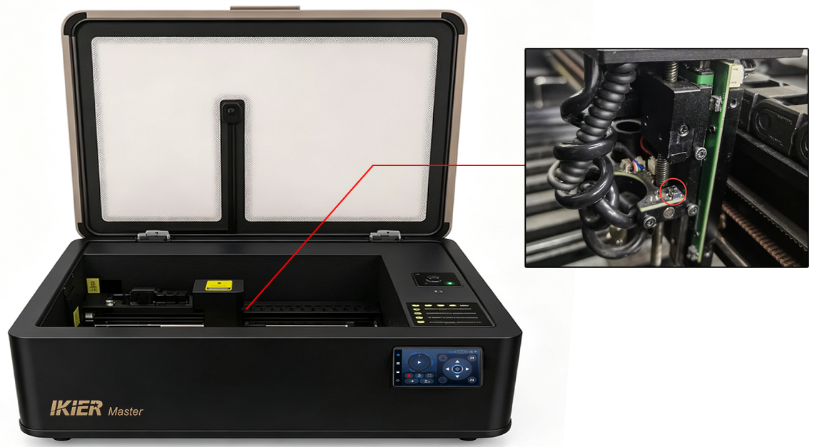
Figure 86
- Check the adapter board wiring:
Open the cover at the top of the Z-axis and check whether any cables on the adapter board are loose.
Disconnect and reconnect the cables, then test again (see Figure 87).
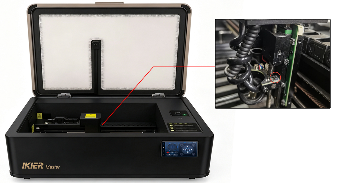
Figure 87
- If the above steps do not resolve the issue, please send the following to customer service:
-
A video showing the issue
-
The troubleshooting steps already performed
-
A photo of the machine’s Serial Number (see Figure 88)
Figure 88
For replacement instructions, please refer to:
-
the Master adapter board replacement guide
-
the Master flame detection board replacement guide