¶ The Master Fails to Home Properly

Solution: Please refer to the Master homing failure troubleshooting video.
Check the homing process:
When the Reset/Home button is pressed, the machine follows this homing sequence:
① Home the Z-axis
② Move the Y-axis
③ Move the X-axis
Please identify at which step the issue occurs and observe the machine behavior. Troubleshoot according to the following steps.
- Check the motor status:
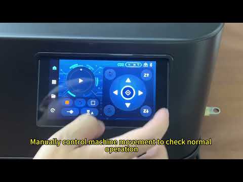
Use the directional buttons on the control screen (see Figure 44) to move the X-axis, Y-axis, and Z-axis motors and check whether they all operate normally.
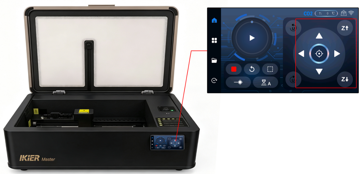
Figure 44
If a motor cannot move properly:
-
Disconnect the motor cable and reconnect it, then test again.
-
Note: Accessing the Y-axis motor requires removing the outer cover. If the Y-axis moves normally, this step is unnecessary.
If the issue persists, please send a video showing the issue, the troubleshooting steps already performed, and a photo of the machine’s Serial Number to customer service for assistance.

For motor replacement instructions, please refer to the Master motor replacement video.
- Check the limit switches:
Check the following limit switches one by one:
-
Z-axis upper limit switch
-
X-axis limit switches (2)
-
Y-axis limit switches (2)
Press each switch and check whether a corresponding trigger notification appears.
If no response is detected, please send a video showing the issue and a photo of the machine’s Serial Number to customer service for assistance.
- Check the machine firmware version:
After connecting through AtomStack Studio or LightBurn, check the firmware version (see Figure 45 and Figure 46).
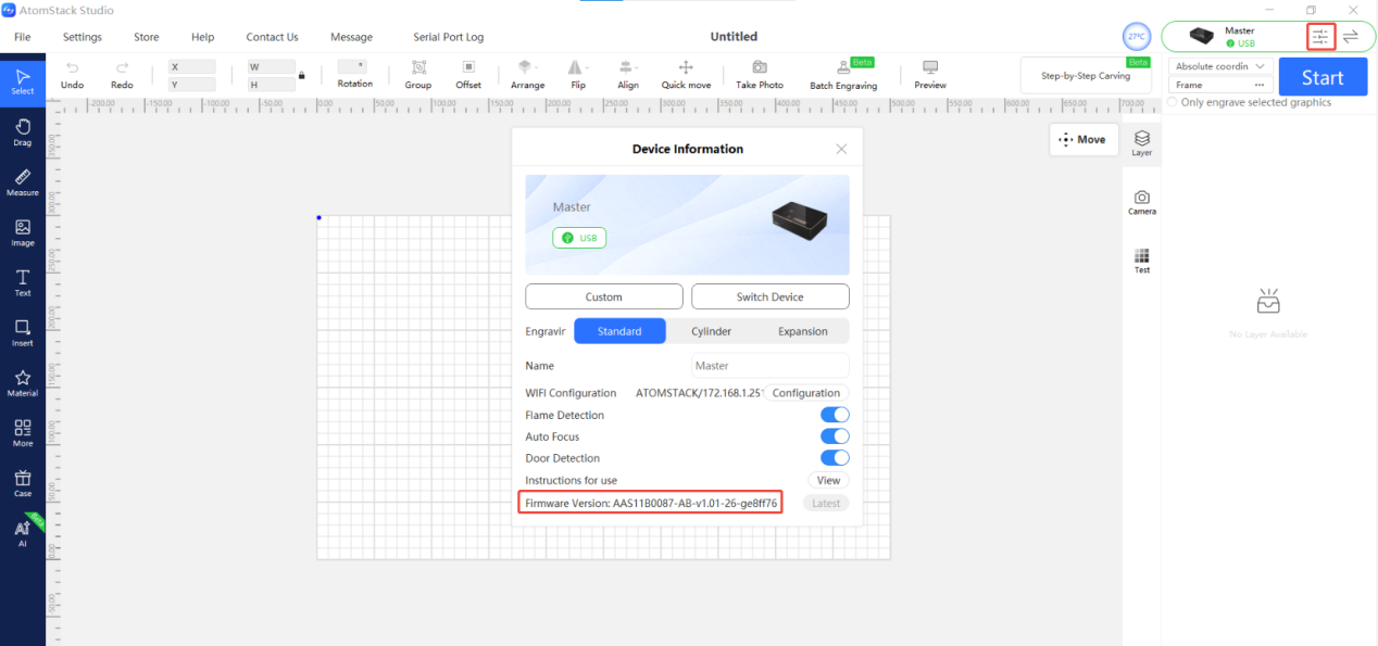
Figure 45
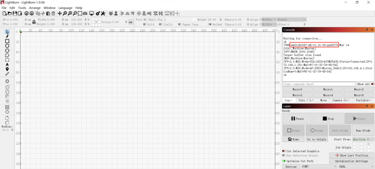
Figure 46
- If the issue still cannot be resolved after completing the above checks, please send the following information to customer service:
-
A video clearly showing the operation steps, machine movements, and any alarm messages
-
The troubleshooting steps already performed
-
A photo of the machine’s Serial Number (see Figure 47) 。
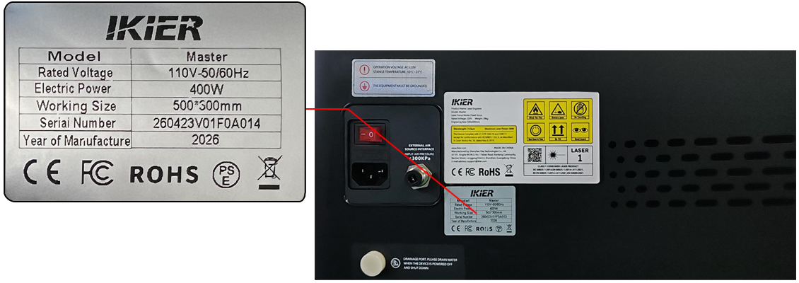
Figure 47
¶ The Master Engraving Output Is Distorted

Solution: Please refer to the Master structural adjustment section.
- Check the timing belts:
Press the X-axis and Y-axis timing belts by hand to check whether they are too loose or too tight. If adjustment is needed, use the belt tensioners located on the right side of the X-axis and the inner side of the Y-axis to adjust the belt tension (see Figure 48).
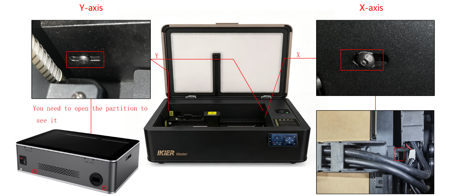
Figure 48
- Check the X/Y timing pulley screws:
To inspect the timing pulley screws, the outer cover and the X-axis motor mounting screws must first be removed. Please refer to the structural adjustment video.
- Check whether the X-axis is parallel to the upper and lower frame edges:
Use a ruler to measure whether the distances from both ends of the X-axis to the lower enclosure frame are equal.
If the distances are inconsistent, adjustment is required. Loosen the coupling screws on the Y-axis motor to make the adjustment. Please refer to the structural adjustment video.
- If the issue still cannot be resolved after completing the above checks, please send the following to customer service for assistance:
-
A video showing the X-axis parallelism measurement
-
A video showing the timing pulley screw inspection
-
A video showing the timing belt inspection
-
A photo of the machine’s Serial Number (see Figure 49).
Figure 49
¶ The Engraved Lines from Master Are Not Fully Closed

Solution: Please refer to the Master open-line troubleshooting section.
- Check the focus distance:
Measure the distance between the bottom of the Z-axis focusing assembly and the material surface to confirm that it is 8 mm.
If the distance is incorrect, refocus the machine. Please refer to the “Master Focus Distance Adjustment” section.
- Check the focusing lens:
Unscrew the focusing lens tube cover and remove the focusing lens to check for dirt or damage(see Figure 50).
If the lens is dirty, clean it using anhydrous ethanol and a lint-free cloth. Please refer to the “Master Focusing Lens Cleaning” section.
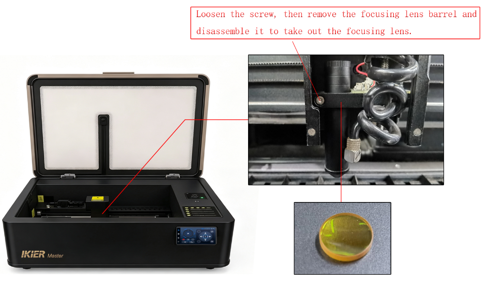
Figure 50
- Check the software parameter settings:
Use the recommended parameter settings for the corresponding material according to the parameter chart. Incorrect parameter settings may result in insufficient laser energy.
Note: The speed unit is mm/min.
How to access the Master parameter chart:
① Scan the QR code on the engraving machine to view it.
② Contact customer service to request the parameter chart.
- Check the laser optical path:
Perform verification and troubleshooting according to the “Master Optical Path Verification and Calibration” section.
- Enable Constant Power Mode:
Turn on the Constant Power function in the software and check whether the issue is resolved(see Figure 51).
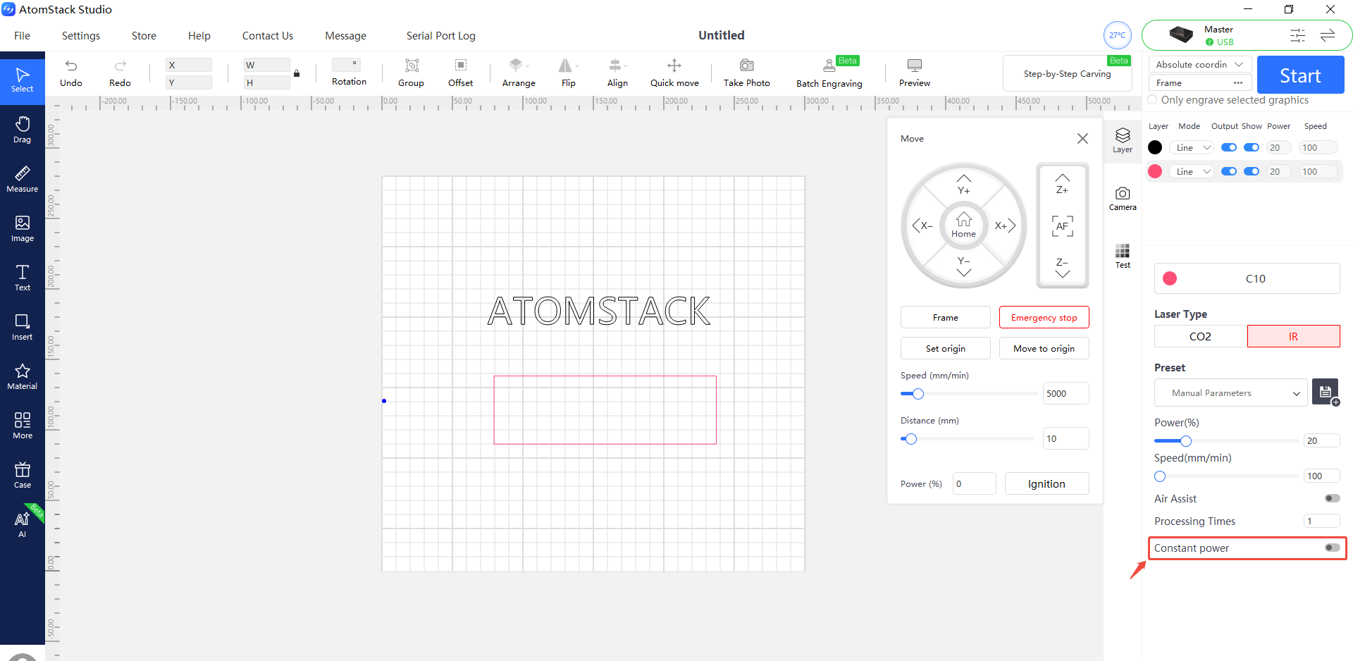
Figure 51
- Adjust the minimum power value ($31):
① In AtomStack Studio:
Open the Settings menu, then continuously left-click the software version field more than 7 times to enable the developer mode menu called “Serial Port Log.”
Open “Serial Port Log,” then enter the following command in the input field:
$31=*(see Figure 52)
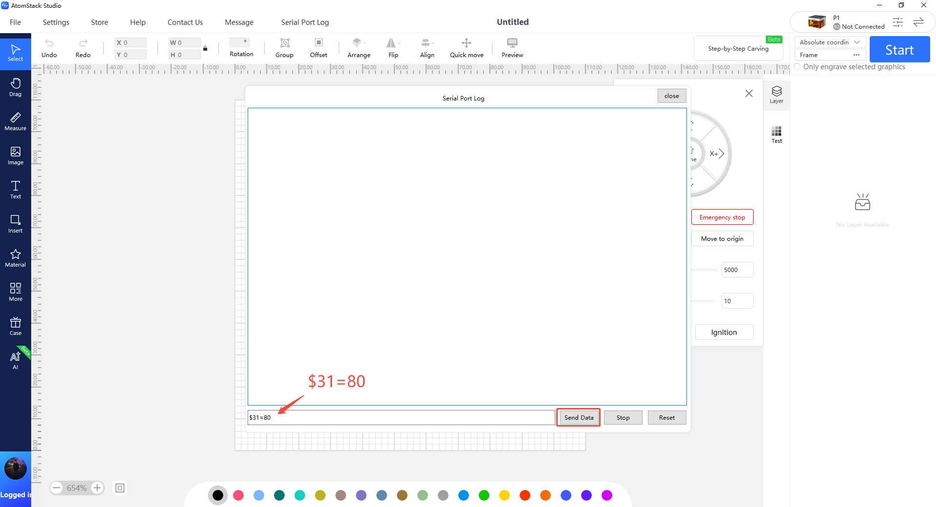
Figure 52
Replace * with a specific value and gradually increase it until the lines close properly.
For example:
If the lines do not close when $31=0, send:
$31=10
If the issue persists, continue increasing the value, for example:
$31=20
Repeat until the engraved lines close properly.
② In LightBurn:
Go to “Edit” → “Machine Settings,” then locate the $31 parameter.
Increase the value, click “Write,” then click “OK” to save the setting.
Repeat this process and continue increasing the $31 value until the lines close properly.
¶ Master Auto Focus Failure

Solution: Please refer to the Master auto focus troubleshooting guide.
- Confirm that the auto focus function is enabled:
After connecting the machine, check whether the auto focus function is enabled in the machine function settings page of AtomStack Studio (see Figure 53).
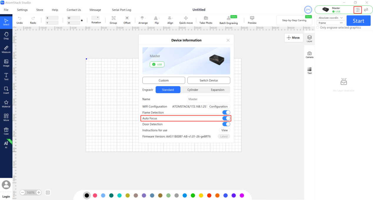
Figure 53
- Confirm that material is placed on the blade bed:
If no material is placed on the bed, the Z-axis may not be able to detect or contact the material properly, which can cause auto focus to fail.
- Confirm the material type:
If the material is soft or flexible, please use the Z-axis movement controls on the control screen to perform manual focusing instead. The focus distance should be 8 mm (see Figure 54).
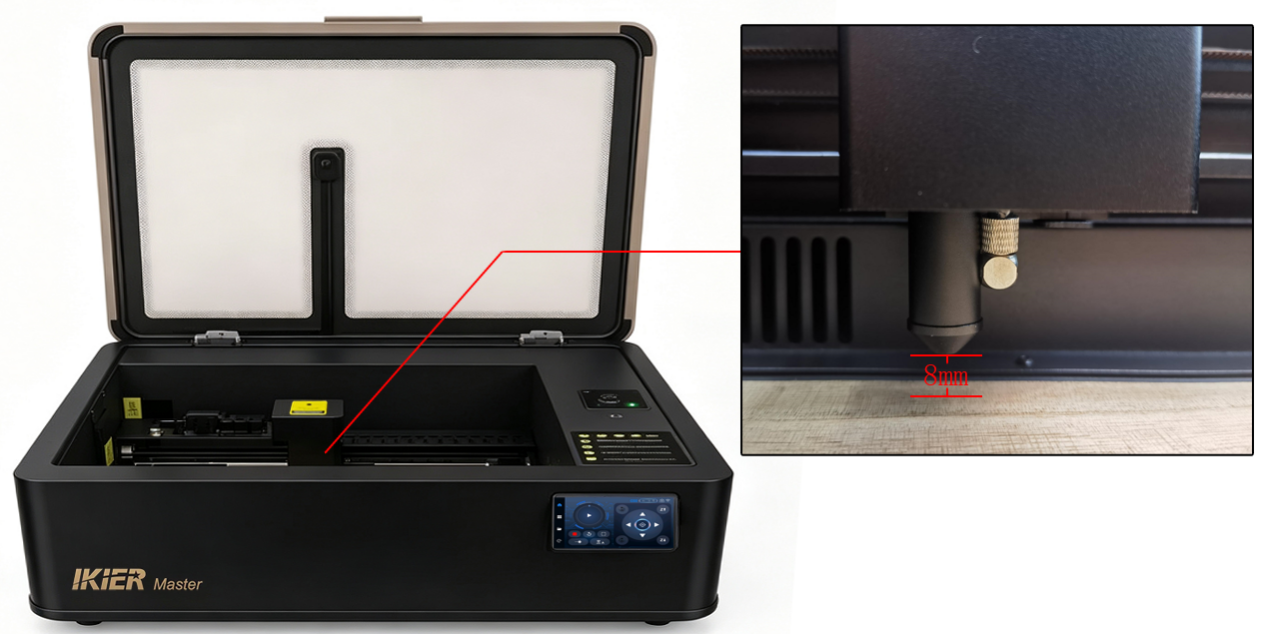
Figure 54
- Check the Z-axis upper and lower limit switches:
- Gently push the focusing lens tube upward by hand to check whether the lower limit switch can be triggered(see Figure 55). If it can be triggered, the lower limit switch is functioning normally.
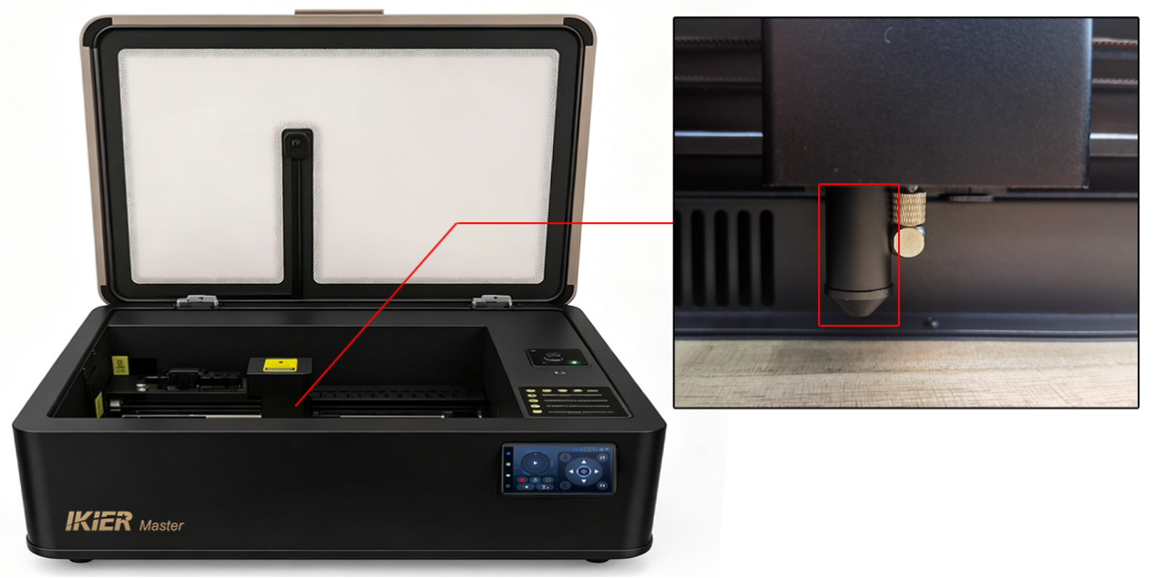
Figure 55
- Use the Z-axis movement controls on the control screen to move the Z-axis upward. When it reaches the top position, check whether the upper limit switch is triggered. If it can be triggered, the upper limit switch is functioning normally.
① If the lower limit switch cannot be triggered properly:
Open the cover at the top of the Z-axis and check whether the lower limit switch cable is loose (see Figure 56).
If the cable connection is normal, the lower limit switch board may be faulty. Please refer to the Master limit switch replacement video for replacement instructions.
② If the upper limit switch cannot be triggered properly:
Open the cover at the top of the Z-axis and check whether the upper limit switch cable is loose (see Figure 57).
Disconnect and reconnect the cable, then manually press the upper limit switch to check whether it can be triggered normally.
If it still cannot be triggered, the upper limit switch board is likely faulty. Please refer to the Master limit switch replacement video for replacement instructions.
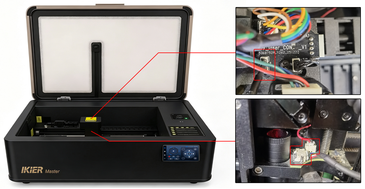
Figure 56
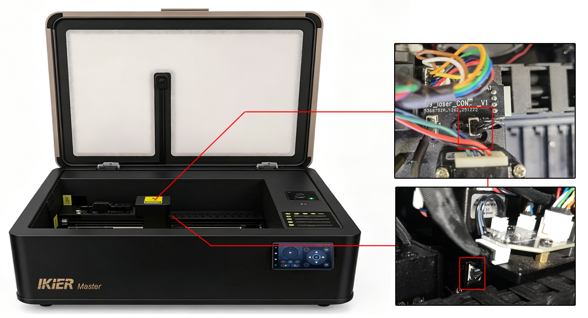
Figure 57
- Check the motor status:
If the Z-axis motor makes noise during the auto focus process but does not move:
-
Use the Z-axis movement controls on the control screen to move the Z-axis up and down and check whether the movement is smooth.
-
If the Z-axis moves smoothly using the control buttons, the issue may be firmware-related. Please send the machine’s Serial Number (see Figure 58), a video showing the issue, and the troubleshooting steps already performed to customer service for assistance.
-
If abnormal behavior also occurs when using the control buttons, open the cover at the top of the Z-axis and check whether the Z-axis motor cable is loose. Disconnect and reconnect the cable. Also check whether the cable is damaged (see Figure 59).
-
If the cable and connector appear normal, manually rotate the Z-axis motor lead screw (see Figure 60) to check whether the Z-axis linear guide rail is functioning properly. If any abnormality is found, please send a video showing the issue to customer service for assistance.
-
Figure 58
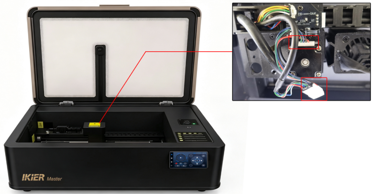
Figure 59
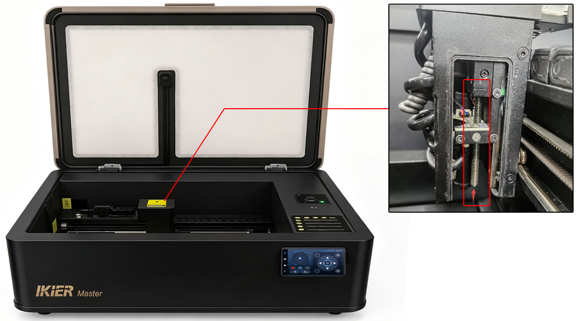
Figure 60
- If the above steps do not resolve the issue, please send the following to customer service:
-
A video showing the auto focus failure
-
A video showing the troubleshooting process
-
The machine’s Serial Number
¶ Master Displays “Travel Limit Reached” During Operation
Solution: Please refer to the Master travel limit troubleshooting guide.
- Check whether a limit switch has been triggered:
Observe under what conditions the alarm appears and whether a limit switch has been physically triggered.
If a limit switch has been triggered, check whether the engraving file size exceeds the machine’s working area:
-
CO₂ mode working area: 500 mm × 300 mm
-
IR mode working area: 300 mm × 265 mm
If no limit switch appears to have been triggered, continue with the following troubleshooting steps.
- Check the limit switches:
Use the control screen to move the machine up, down, left, and right, and check whether all X-axis and Y-axis limit switches can be triggered properly.
You can also move the Z-axis to confirm whether all three Z-axis limit switches can be triggered normally.
If any switch cannot be triggered, or if the alarm appears during movement, follow these steps:
-
First, confirm that the limit switch cables are securely connected. Disconnect and reconnect the cables.
-
Check whether the limit switches have any physical damage.
- Check the machine firmware version:
In AtomStack Studio or LightBurn, check whether the machine firmware version is correct (see Figure 61 and Figure 62).
If the firmware version is not the latest version, please update it to the latest release.
Figure 61
Figure 62
- If the above steps do not resolve the issue, please send the following to customer service:
-
A video showing the issue
-
The troubleshooting steps already performed
-
A photo of the machine’s Serial Number (see Figure 63)
Figure 63
¶ The Master Stops During Engraving

Solution: Please refer to the Master engraving interruption troubleshooting guide.
- Check the software alarm messages:
After the machine stops, check whether the software displays any error or alarm messages. If there is an error message, troubleshoot according to the prompt.
- Travel Limit Reached
Please refer to the section: “The Master Displays ‘Travel Limit Reached’ During Operation.”
- Alarm 1
A limit switch has been triggered. Check carefully whether the engraving file exceeds the machine’s working area, or whether the machine has collided with a limit switch during operation.
- Alarm 3
The machine detected an automatic stop signal or another stop condition. Further troubleshooting is required based on the specific trigger condition.
- Alarm 12
A flame alarm has been triggered. Please check the following:
-
Whether the engraving/cutting material is MDF, balsa wood, or similar materials
-
Try replacing the material with basswood for testing
-
Check whether the engraving/cutting design contains overly dense lines; if so, increase the speed and increase the number of engraving/cutting passes
-
Check whether direct sunlight is shining into the machine, as direct sunlight may falsely trigger the flame alarm
-
Alarm 13
The enclosure door is open. Check whether the enclosure door was opened during engraving.
If the door was not opened, the enclosure door limit switch may be faulty. Please send a video showing the issue, the alarm message, and the machine’s Serial Number to customer service for assistance.
If replacement is required, please refer to the Master limit switch replacement video.
- If no alarm message is displayed, continue with the following troubleshooting steps.
- Check the engraving progress bar in the software:
If the engraving progress bar in the software continues running even though the machine has stopped, the issue may be caused by abnormal data transmission.
Try the following:
-
Use a different USB port on the computer
-
Replace the Type-C cable
-
Try a different engraving software (such as AtomStack Studio or LightBurn)
- If the above steps do not resolve the issue, please send the following to customer service:
-
A video showing the issue
-
Screenshots of any software messages or alarms
-
The troubleshooting steps already performed
-
A photo of the machine’s Serial Number (see Figure 64)
Figure 64
¶ The Master Does Not Respond After Pressing the Start Button
- Check the machine status:
-
Home the machine first
-
Make sure the enclosure door is closed
-
Confirm that the water tank has been filled and that the water level is above the minimum level
-
Check the machine temperature displayed in the software
- Check the connection status:
Use the directional controls in the software to move the machine and check whether the connection has been disconnected.
- Check for software prompts:
After pressing the Start button, check whether any message or warning appears in the software. If a prompt appears, troubleshoot according to the message.
- Check the control screen information:
Check whether any alarm or warning message is displayed on the control screen.
- Restart the machine and software:
Close the machine and the software completely, then restart both and try again.
- Try different software:
Try using a different control software, such as AtomStack Studio or LightBurn.
- If the above steps do not resolve the issue, please send the following to customer service:
-
A video showing the issue
-
Screenshots of any software prompts or error messages
-
The troubleshooting steps already performed
-
A photo of the machine’s Serial Number (see Figure 65)
Figure 65
¶ The Distance After Master Auto Focus Is Not 8 mm
- Confirm the material type:
If the material is soft or flexible, please use manual focusing instead. The correct focus distance is 8 mm.
Use the Z-axis movement controls on the control screen to adjust the height manually. It is recommended to use Jog Mode for more precise adjustment.
- Confirm the auto focus process:
The auto focus sequence works as follows:
-
The Z-axis first moves to the highest position
-
Then moves downward until the lower limit switch is triggered
-
Finally moves upward to the standard 8 mm focus height
If the auto focus process appears normal but the final distance is not 8 mm, you can adjust the auto focus distance parameter in LightBurn or LaserGRBL.
The default auto focus parameter value is 1.5.
Correction value calculation:
- If the actual measured distance is greater than 8 mm:
[
1.5 - (\text{actual measured value} - 8)
]
- If the actual measured distance is less than 8 mm:
[
1.5 + (8 - \text{actual measured value})
]
In the LightBurn Console window (see Figure 67), enter:
$autoFocus/depth_max_mm=correction_value
Then press Enter.
Example:
If the actual auto focus distance measures 9 mm, then:
[
1.5 - (9 - 8) = 0.5
]
So the command should be:
$autoFocus/depth_max_mm=0.5

For detailed operation steps, please refer to the Master auto focus distance adjustment guide.
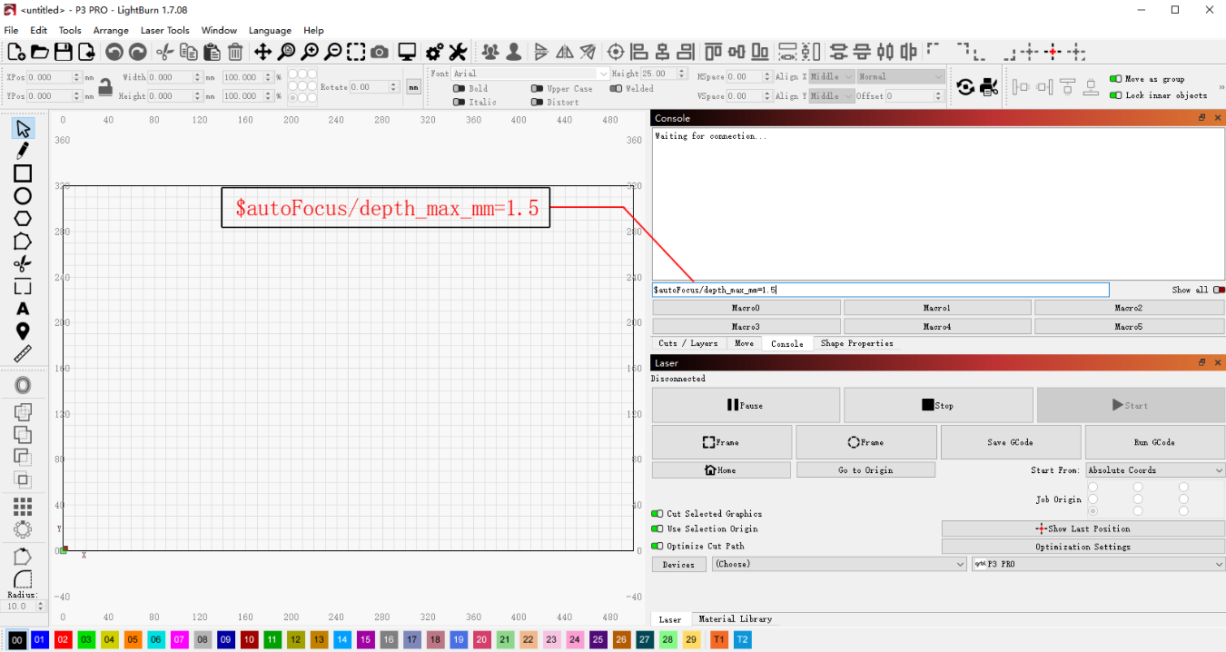
Figure 67
¶ Master Timing Belt Is Broken
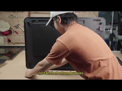
Solution: Please refer to the Master timing belt replacement video.
Note
Replacing the Y-axis timing belt requires removing the outer cover.
When replacing the X-axis timing belt, loosen the timing belt tensioner first.