How to Use Flex Pro – Setup & Touchscreen
Follow these sections for installation, computer or mobile connection, touchscreen use, laser switching, and focusing.
¶ Setup & Connection
¶ Unboxing & Setup
Unboxing and Installation
Follow the Flex Pro unboxing and installation video for instructions.
Note
1) Check the Accessories: After unboxing, check all accessories against the video or user manual to ensure that nothing is missing.
2) Connect Correctly: Follow the video instructions to connect all interfaces during installation, ensuring that each connector is connected to the correct port.
3) Check the USB Key: The USB Key must be inserted into the designated key port on the machine to unlock the laser for use. Make sure it is properly inserted.
¶ Control Panel
- Control Panel Overview
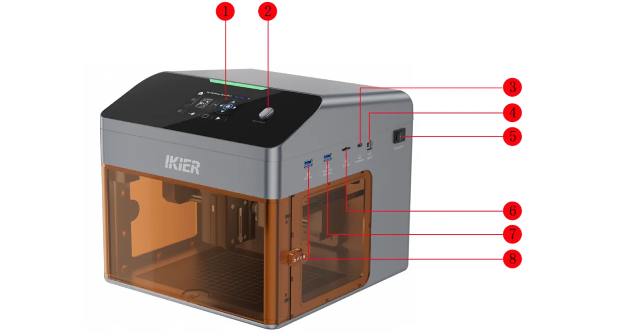
1) Touchscreen
The main control screen. Supports offline engraving, network configuration, engraving file creation, image uploads, and other operations.
2) Start/Pause
- Short press: Start or pause engraving.
- Long press: Reset the network.
3) Computer (Type-C Port)
Connect the machine to a computer using a Type-C data cable.
4) Input (Power Port)
Input rating: 24V / 3A.
5) Emergency (Power Switch)
Controls the power on/off of the laser engraver.
6) TF Card (TF Card Slot)
A 4GB or 8GB TF card is recommended. The capacity should not exceed 16GB.
7) Accessory Interface
Used to connect R6, R8, and R8 Pro rotary attachments.
Note
Class 1 models do not support rotary accessories, as the base plate is non-removable. (This model is certified as a Class 1 laser product under IEC 60825-1.)
8) USB Key (USB Key Port)
Insert the USB Key to unlock the machine. If the USB Key is not inserted, the machine will remain in an alarm state and cannot be used.
¶ Computer Connection
- Connecting to a Computer
Follow the Flex Pro computer connection video for instructions.
Operating Procedure:
1) Connect the Device
A Type-C data cable is recommended. Connect the Type-C end to the “Computer” port on the machine.
Note
Computer System Compatibility
- Windows: Connect directly using a Type-C-to-USB-A or USB-C port.
- macOS / HarmonyOS: A hub or docking station (as shown in Figure 1) is required. Connect via the USB-A port on the hub. Direct connection via the USB-C port is not supported.
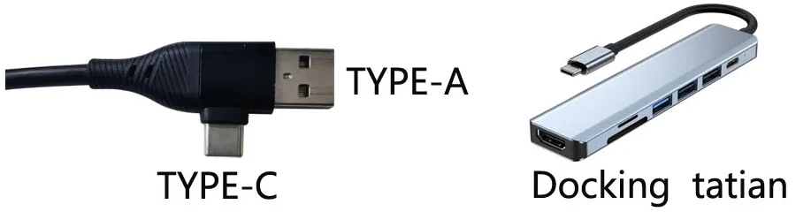
Figure 1
2) Install the Serial Port Driver
The serial port driver must be installed before using the software for the first time. Download the driver from the links below.
- Windows driver download: https://asa.atomstack.com/downloadWindowsDrivers.do3
- macOS driver download: https://asa.atomstack.com/downloadMacDrivers.do3
After installation, check Device Manager on your computer. If the “CH340” serial port appears (as shown in Figure 2), the driver has been installed successfully.
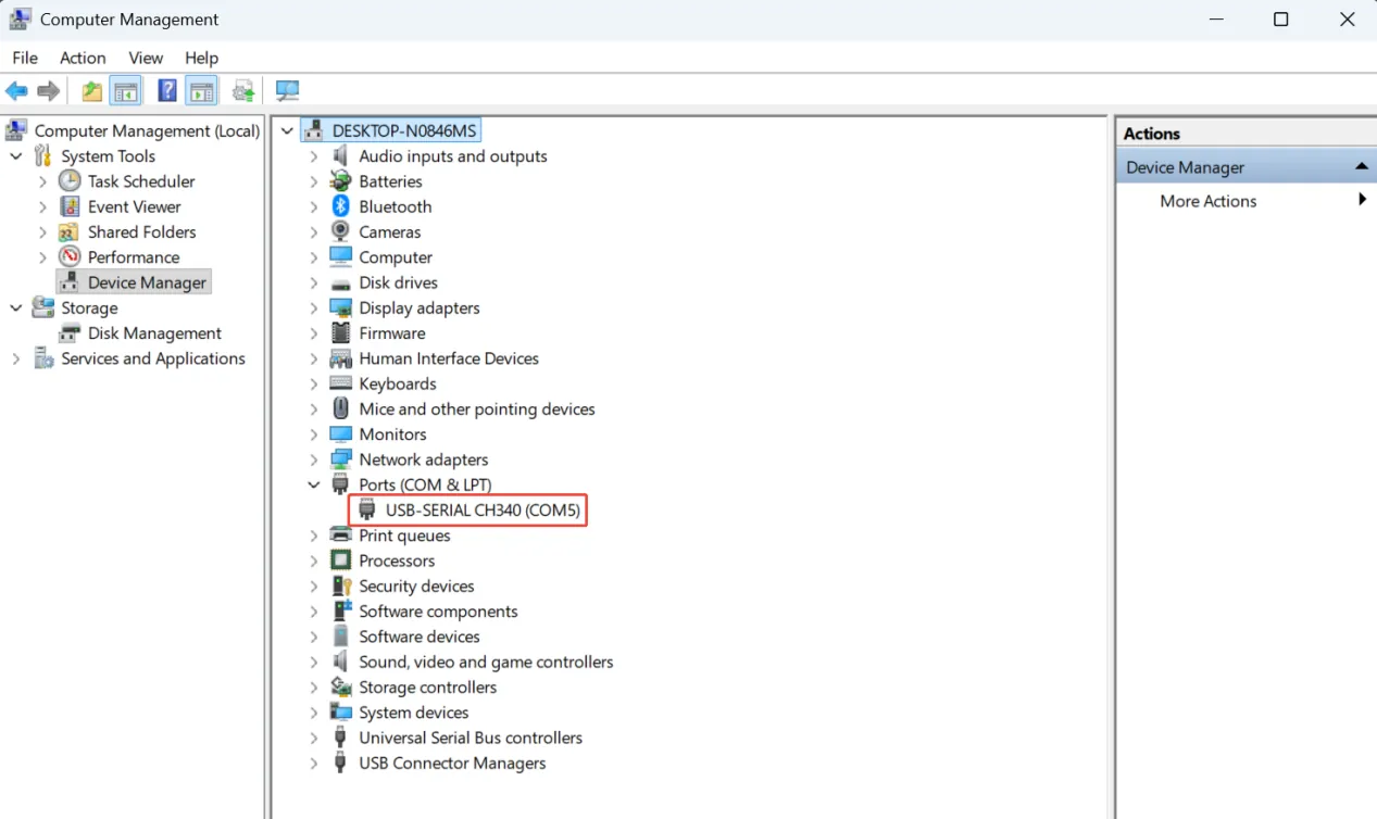
Figure 2
3) Install the Control Software
AtomStack Studio or LightBurn is recommended.
- Download AtomStack Studio: https://atomstack.com/pages/software-guide
- Download LightBurn: https://lightburnsoftware.com/pages/download-trial
4) Software Configuration
① AtomStack Studio
The software automatically recognizes the machine model, so no additional configuration is required.
② LightBurn
Import the Flex Pro configuration file or configure the settings manually.
For manual configuration:
- Manually add a “GRBL” controller.
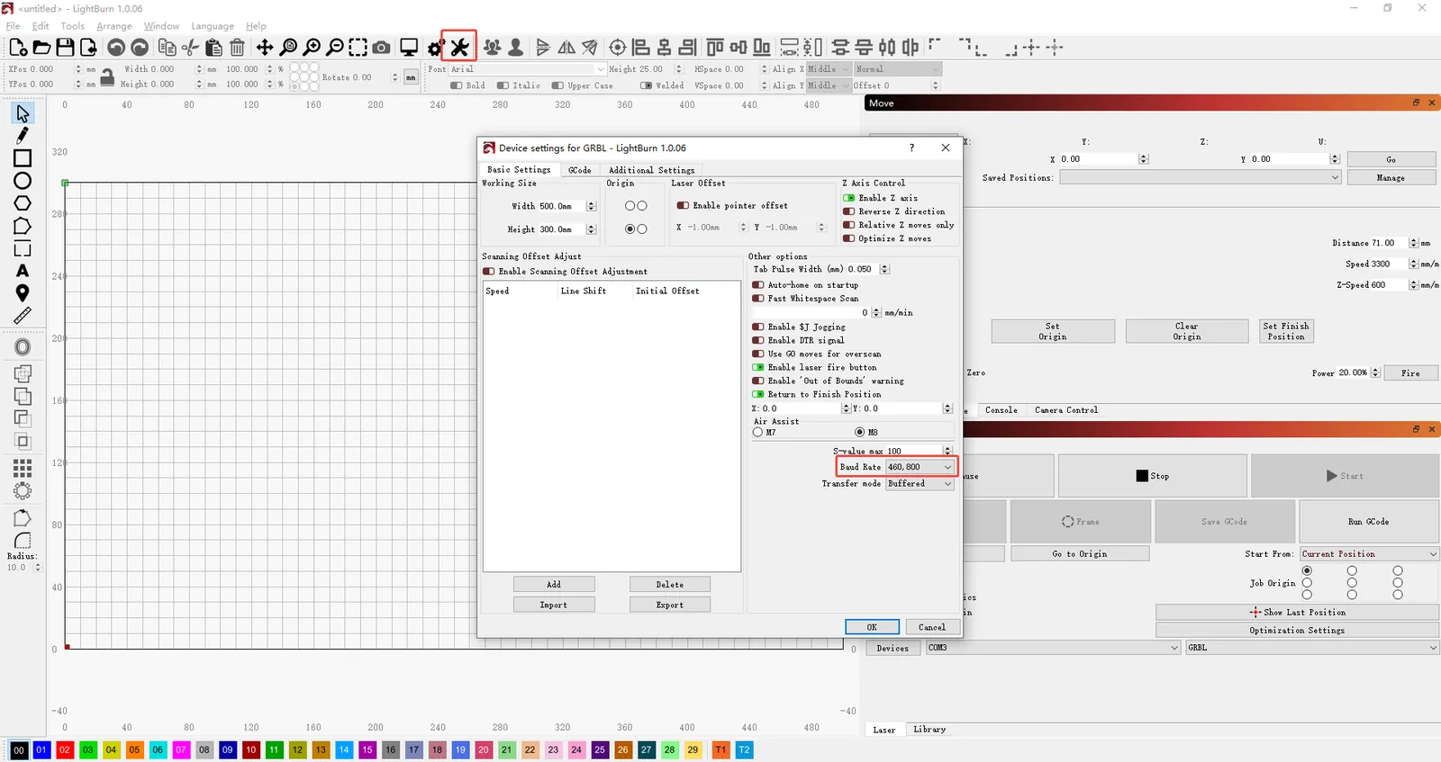
Figure 3
-
A baud rate of 460800 is recommended. Other baud rates may also work correctly, as shown in Figure 3.
-
Set the engraving area according to the laser type: 110 mm × 110 mm for the diode blue laser or 105 mm × 100 mm for the infrared laser.
¶ Mobile Connection
- Connecting via the Mobile APP
Follow the Flex Pro mobile APP connection video for instructions.
Note
Flex Pro supports three mobile APP connection modes: Bluetooth, Wi-Fi, and IP.
Bluetooth mode is recommended as the preferred option because it is easier to use.
1) Connection Methods
①Bluetooth Mode (Recommended)
- Activation via Button: Press and hold “Start/Pause” to enter Bluetooth pairing mode. The indicator light on the top of the machine will flash blue.
- Activation via Touchscreen: On the touchscreen, go to “Settings” → “Wireless Connection” → “Bluetooth Connection,” then tap “Activate Bluetooth” → “Activate” to enable Bluetooth mode. After activation, the indicator light on the top of the machine will also flash blue.
② Wi-Fi Mode
On the touchscreen, go to “Settings” → “Wireless Connection” → “Wi-Fi Connection.” The screen will display all detected Wi-Fi network names. Select the Wi-Fi network name corresponding to your router and connect. Once connected successfully, use the Wi-Fi module in the APP to search for and connect to the machine.
③ IP Mode
After configuring the Wi-Fi network on the touchscreen, the screen will display the current router's Wi-Fi network name and the machine's IP address, as shown in Figure 4. Enter the machine's IP address in the IP module of the APP to connect.
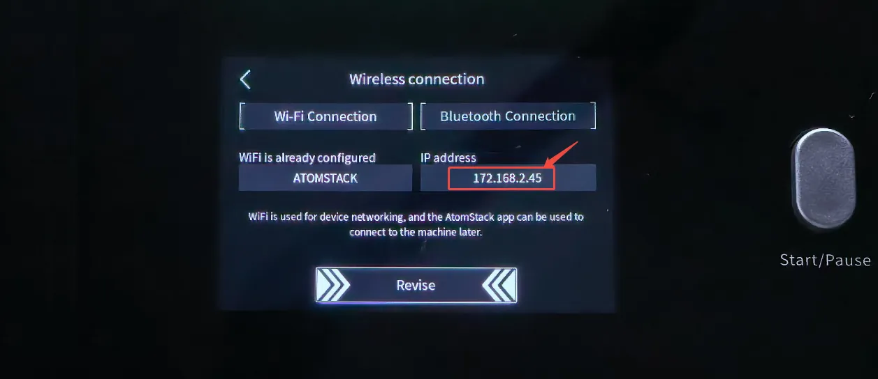
Figure 4
2) Requirements for Use
- A TF card must be inserted before using the mobile APP to control engraving or cutting.
- A 4GB or 8GB TF card is recommended, and the capacity should not exceed 16GB to ensure reliable file reading and writing.
Note
For first-time use, Bluetooth mode is recommended because it is easy to set up and does not require additional network configuration.
- Open the mobile APP and select Bluetooth mode to search for and pair with the machine.
¶ Touchscreen
¶ Touchscreen Operation
The touchscreen functions are continuously being improved and updated. This document is based on the following versions for reference. For instructions on using the relevant functions, refer to the Flex Pro touchscreen tutorial video.
Firmware Version: V1.03
System Version: IKIER OS V0.2.1
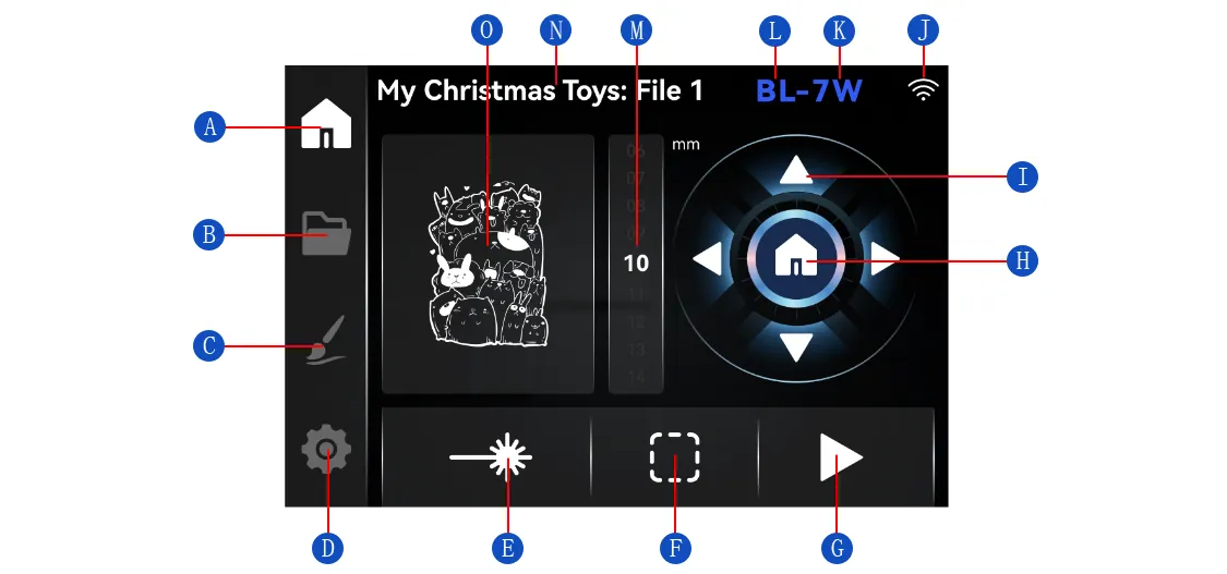
1) Home
| No. | Name | Description |
|---|---|---|
| A | Home Icon | Tap to enter the Home screen. |
| B | Files Icon | Tap to enter the Files screen, where you can select files saved on the TF card for engraving. |
| C | Create Icon | Tap to enter the Create screen, where you can select from the local sample library, enter text, or use the freehand drawing function. |
| D | Settings Icon | Tap to enter the Settings screen to configure relevant settings. |
| E | Laser Fire Button | Tap to activate the blue laser at low power for positioning. This function is disabled when an infrared laser is connected. |
| F | Frame Button | Tap to make the laser engraver trace the boundary of the current design. The blue laser automatically emits a low-power laser beam during framing. |
| G | Start Button | Tap to start engraving the current file and enter the Processing screen. |
| H | Reset Button | Tap to return the laser to its home position and reset the laser engraver. |
| I | Directional Control Buttons | Used to move the laser module forward, backward, left, and right. |
| J | Wireless Connection Mode | Displays the current wireless connection mode (Bluetooth or Wi-Fi). |
| K | Laser Power Display | Displays the default laser power of the current machine: blue “7W” or “12W,” or red “1.4W.” |
| L | Laser Type Display | Displays the type of connected laser: “BL” for the diode blue laser or “IR” for the infrared laser. |
| M | Movement Step Adjustment | Adjusts the distance moved with each press of a directional control button. The available range is 1–20 mm. |
| N | File Name | Displays the name of the current processing file. |
| O | Pattern Preview | Displays the current pattern to be processed. |
2) Files
Tap to enter the Files screen, where you can view and delete all recognized processing files on the TF card.
- View: Select a file and tap it to enter the engraving screen (Home screen).
- Delete: Long-press a file to enter the “Delete File” screen.
Note
The touchscreen cannot recognize .GC or .NC files. In AtomStack Studio, select the “Back up files to local machine” option and start engraving. Once the file has been uploaded, you can find it in Files.
3) Create
The Create screen includes the following functions:
① Local Examples
You can select examples stored on the touchscreen’s TF card for engraving. Some examples are preloaded on the touchscreen’s TF card before the machine leaves the factory.
Note
The touchscreen’s TF card and the mainboard’s TF card are two separate cards. The contents of the touchscreen’s TF card cannot be accessed in Files, and the contents of the mainboard’s TF card are not displayed in the Local Examples list.
② Text
Enter text here to create an engraving file.
③ Freehand Drawing
Tap to enter the Freehand Drawing screen, where you can draw a processing file. Once finished, tap “√” in the upper-right corner to enter the“Parameter Settings”screen.
Note
Functions of the Parameter Settings Screen:
| Function | Description |
|---|---|
| Material Selection | Select from a variety of materials, each with preset parameters available for use. |
| Engraving Effect Selection | Select from a variety of engraving effects, including preset effect images. |
| Modify Parameters | Select Fill or Line mode and adjust parameters such as power, speed, and number of passes. |
| Frame | The laser engraver frames the current file boundaries. The diode blue laser automatically emits a low-power laser beam for positioning. |
| Start | Tap to start processing the current file. The laser engraver then enters the Processing screen. |
4) Settings
① Language
The current version supports switching between 11 languages: English, Chinese, Italian, Spanish, French, Korean, Japanese, Russian, German, Portuguese (Brazil), and Portuguese (Portugal).
② Wireless Connection
The current version supports two connection modes: Wi-Fi and Bluetooth.
- Wi-Fi Connection: After entering this screen, all detected Wi-Fi network names will be displayed. Select the Wi-Fi network corresponding to your router and connect. Once connected successfully, you can find and connect to the device through the Wi-Fi module in the mobile app.
- Bluetooth Connection: Bluetooth mode can be activated in either of the following two ways.
- Long-press the“Start/Pause”button to enter Bluetooth pairing mode. The indicator light on the top will flash blue.
- Alternatively, on the touchscreen, tap“Settings”→“Wireless Connection” → “Bluetooth Connection,” then tap “Activate Bluetooth”→“Activate”in sequence to enable Bluetooth mode. After activation, the indicator light on the top will also flash blue.
- Open the mobile app and select Bluetooth mode to search for and pair with the machine.
③ Notifications
All alarm messages can be viewed here. Note that all messages will be cleared when the machine restarts.
④ Machine Settings
- Laser Power Selection: Select either 7W or 12W. The machine is preset at the factory. If you purchase a different laser module separately, select the corresponding laser power here. The infrared laser module has an automatic identification chip and does not require manual configuration.
Note
The power selection here affects how AtomStack Studio and the mobile app identify the machine, but does not affect LightBurn.
- Button Sound: Enable or disable button sounds here.
⑤ Transfer Images from Phone
The device’s hotspot name is displayed on the “Transfer Images from Phone” screen. You can search for and connect to the device’s hotspot directly from your phone. Once connected, the upload screen will open automatically, allowing you to upload files and images. If the upload screen does not open automatically after connecting to the hotspot, use your browser to scan the QR code displayed on the screen to access the upload screen manually.
Note
If you scan the QR code directly with your browser without connecting to the device’s hotspot first, a “LanSwitch” login screen may appear. This is the wrong procedure. Connect to the device’s hotspot before scanning the QR code.
⑥ System Update/Reset
This screen displays the current firmware and system versions. Tap the “System Reset” button at the bottom to reset the system.
¶ Laser Module
¶ Replace the Laser
Replacing the Infrared/Diode Blue Laser Module
Refer to the Flex Pro Infrared/Diode Blue Laser Module Replacement video for instructions.
1) Removal Steps
- Turn Off the Power: Before replacing the laser module, turn off the laser engraver to ensure safe operation.
- Remove the Laser Module: Loosen the knurled screw securing the laser module, remove the module, and disconnect its cable.
2) Installation Steps
- Loosen the Knurled Screw: Before installing the laser module, loosen the knurled screw to prevent it from obstructing the module as it is inserted into the slider.
- Install and Secure the Laser Module: Position the laser module correctly, then tighten the knurled screw.
¶ Laser Focusing
Laser Module Focusing Instructions
Refer to the Flex Pro Laser Module Focusing video for instructions.
Operating Steps:
1) Position and Secure the Material
Place the material flat on the worktable. For lightweight materials (such as paper or thin wood boards), it is recommended to secure all four corners with magnets to prevent the material from moving.
2) Loosen the Laser Module and Swing the Focusing Rod Down
Loosen the knurled screw to allow the laser module to slide up and down. Then swing the focusing rod on the side of the laser module down and adjust the module height until the end of the focusing rod lightly touches the material surface, as shown in Figure 5.
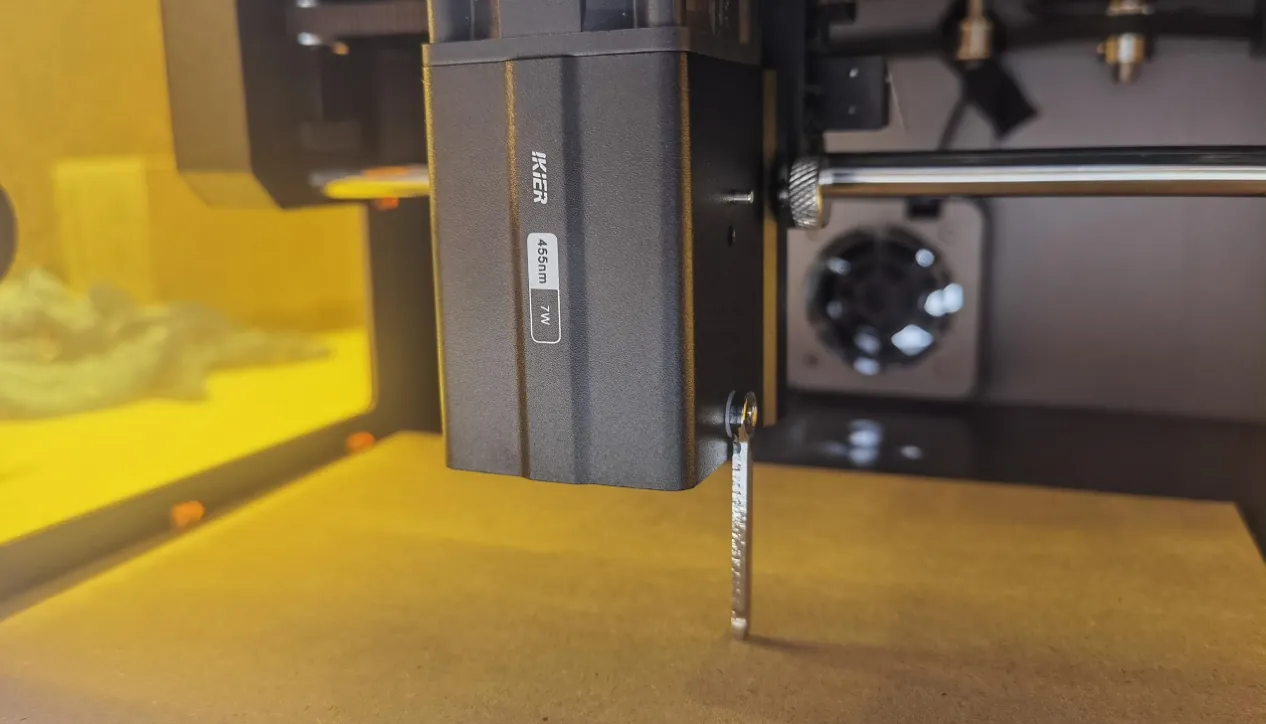
Figure 5
3) Secure the Laser Module and Swing the Focusing Rod Back Up
Tighten the knurled screw to secure the laser module at this height. Finally, swing the focusing rod back up to its original position to complete focusing.
Caution
Do not overtighten the knurled screw. Tighten it just enough to keep the laser module securely in place. Excessive force may damage the threads or slider.
When swinging the focusing rod down, lightly touch the material surface only. Do not press down hard, as this may deform the material or displace the focusing rod.
¶ IR Crosshair Setup
- Infrared Laser Crosshair Calibration
Please refer to the Flex Pro Infrared Laser Crosshair Calibration Video and follow the steps below.
1) PC Software Operation Steps
① Home the Engraving Machine
After successfully connecting, home the machine first to ensure the coordinates are reset to zero.
② Enter the Calibration Interface
Open Device Information in the upper-right corner of the software and confirm that Positioning Mode is set to Red Cross Positioning.
Click the Calibrate button next to Red Cross Positioning Calibration to open the crosshair calibration interface (see Figure 6).
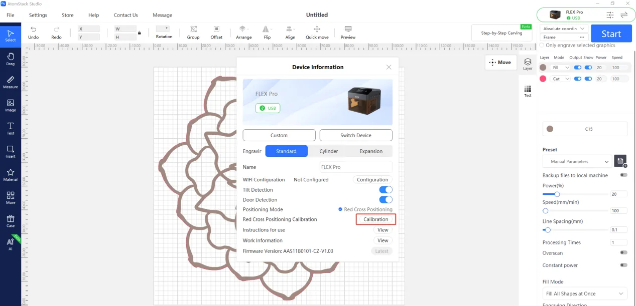
Figure 6
③ Frame to Confirm the Engraving Area
Click Frame to confirm that the calibration pattern is within the engraving area.
④ Execute Engraving
Click Start. The machine will engrave a “+” pattern as the calibration reference.
⑤ Align the Crosshair with the “+” Pattern
Follow the on-screen prompts and use the direction keys to adjust the laser head position until the red crosshair fully overlaps the engraved “+” pattern.
If each movement step is too large, manually adjust the step value to enable finer control.
⑥ Complete Calibration
Click Finish. The system will save the calibration result.
2) Mobile App Calibration
① Open the Calibration Interface
On the App home page, tap Settings in the upper-right corner or in the bottom menu bar to open the device settings page.
② Mark the Current Position
Tap Red Cross Positioning Calibration. In the Mark Current Position pop-up, tap the center of the circle. The machine will automatically engrave a “+” mark as the calibration reference.
③ Align the Crosshair with the “+” Pattern
After engraving is complete, follow the on-screen prompts and use the direction keys to move the laser head until the red crosshair fully overlaps the engraved “+” pattern.
If each movement step is too large, manually adjust the step value for finer control.
④ Complete Calibration
After confirming that the crosshair fully overlaps the “+” pattern, tap Finish. The system will automatically save the calibration result.
¶ Software Coordinates
¶ Coordinate Systems
- Introduction to Software Coordinate Systems
Current Position: Uses the laser module's current position as the engraving start point. You can manually move the laser module to any desired engraving position.
User Origin: The user sets the position where the laser starts working. Refer to the User Origin Setup video.
Absolute Coordinates: Uses the (0, 0) coordinates established during homing as the starting point. The laser starts working at the coordinates specified in the processing file.