¶ K2 Pro Machine Operation
Setup, control panel, connection, focusing, camera, conveyor feeder, rotary, air assist, and batch engraving.
¶ Unboxing and Installation
Please refer to the K2 Pro Unboxing and Installation Video for detailed instructions.
Installation Guidelines:
1. Check the Accessories: After unboxing, check all accessories one by one against the video or user manual to ensure that nothing is missing.
2. Connect the Cables: Follow the instructions in the video to connect all cables. Make sure that the Type-C cable, fire-extinguishing air assist cable, and other cables are connected to the corresponding ports.
3. Install the Accessories: Follow the instructions in the video to connect the USB Key, USB flash drive, and air assist hose to their corresponding ports.
4. Install the Laser Module: Make sure that the two grooves on the laser module base are fully engaged with the two support posts on the Z-axis.
5. Add Water to the Fire-Extinguishing Air Assist System: Refer to the video and fill the fire-extinguishing air assist system with purified water or distilled water as the extinguishing liquid.
¶ Control Panel Overview
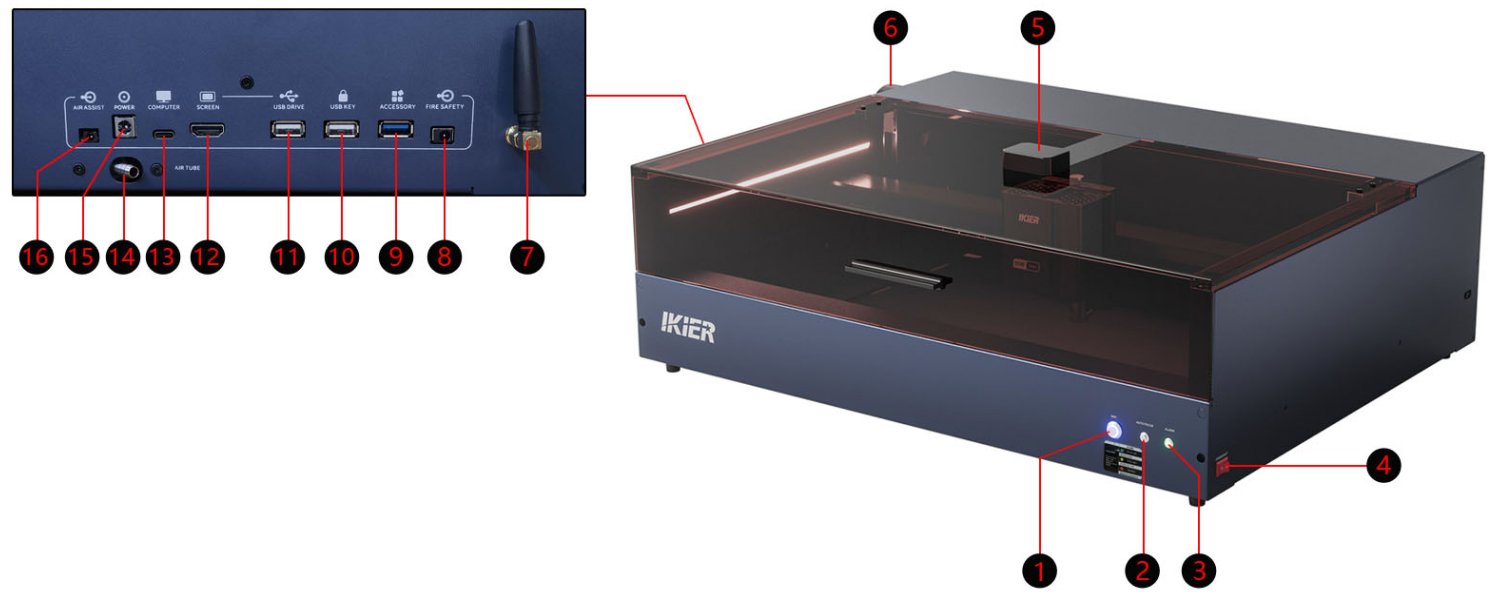
1. Wi-Fi (Wi-Fi Button)
Press and hold for more than 5 seconds to enter Wi-Fi configuration mode.
2. AUTO FOCUS (Auto Focus Button)
Press to perform automatic focusing.
3. ALARM (Status Indicator)
- Solid green: Normal mode. The machine is operating normally.
- Solid yellow: Accessory mode. An expansion accessory, such as the R6, R8, or R7, is connected.
- Solid red: Alarm status. The machine has triggered an alarm.
4. EMERGENCY (Power Switch)
Controls the power on/off of the engraver.
5. Camera
The machine has a built-in camera for visual positioning.
6. Enclosure Fan
The built-in exhaust fan is used to remove smoke and fumes from the enclosure.
7. Wi-Fi Antenna
The Wi-Fi antenna is used to enhance the Wi-Fi signal.
8. FIRE SAFETY (Automatic Fire-Extinguishing Pump Port)
Power control interface for the automatic fire-extinguishing air pump. When a flame alarm is triggered, it automatically outputs voltage to start the fire-extinguishing air pump.
9. ACCESSORY (Expansion Accessory Port)
An automatic accessory detection port. Use the supplied USB cable to connect expansion accessories such as the R6, R8, and R7, which are equipped with automatic identification chips.
10. USB KEY (USB Security Key Port)
Insert the USB Key to unlock the machine. If the USB Key is not inserted, the machine remains in alarm status and cannot be operated.
11. USB DRIVE (USB Flash Drive Port)
A 4 GB or 8 GB USB flash drive is recommended. USB flash drives with a capacity of more than 16 GB are not recommended.
12. SCREEN (Touchscreen Port)
Connect the CR1 Control Panel via an HDMI cable. The CR1 Control Panel is sold separately and is not included as a standard accessory.
13. COMPUTER (Computer Connection Port)
Connect the machine to a computer using a Type-C data cable.
14. AIR TUBE (Air Assist Hose Port)
Connect an external air assist system using the air assist hose.
15. POWER (Power Input Port)
Power adapter input port. Rated input: 24 V / 10 A.
16. AIR ASSIST (Air Assist Power Control Port)
Air assist power control port. During engraving or cutting, the port automatically outputs power to activate the air assist system.
¶ Computer Connection
Please refer to the K2 Pro Computer Connection Video for detailed instructions.
Operation Steps
1. Connect the Device
Use the included Type-C cable to connect the Type-C end to the “COMPUTER” port on the machine. When connecting to a computer, note the following:
- Windows: You can connect the machine directly to the computer using a Type-C-to-USB-A or Type-C-to-USB-C cable.
- macOS or HarmonyOS: You must use a hub/docking station (as shown in Figure 1) and connect the machine using the USB-A port. Direct connection using the Type-C port is not supported.
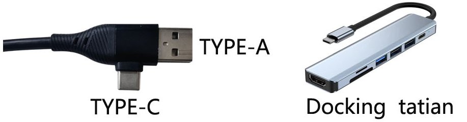
Figure 1
2. Install the USB-to-Serial Driver
The USB-to-serial driver must be installed before using the machine for the first time. Download the appropriate driver from the links below:
- Windows Driver: Download Windows Driver.
- macOS Driver: Download macOS Driver.
After installation, open “Device Manager”. If a “CH340” serial port is displayed, as shown in Figure 2, the driver has been installed successfully.
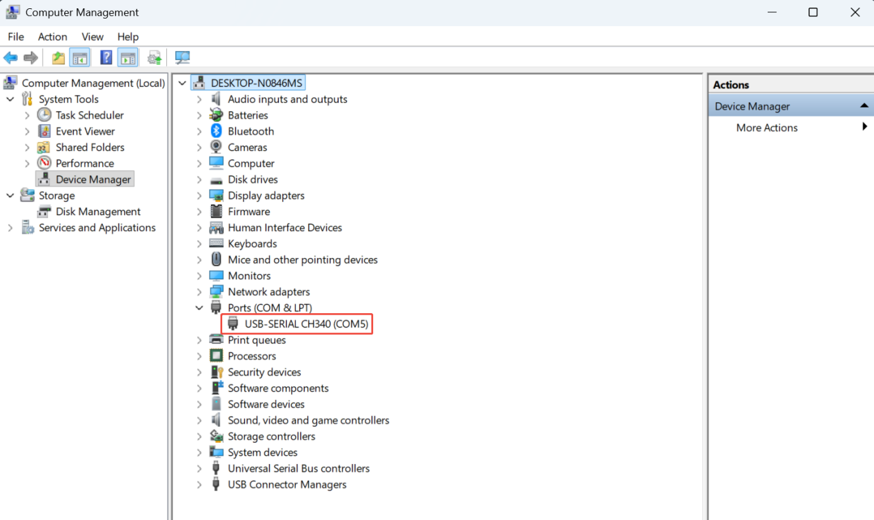
Figure 2
3. Install the Control Software
AtomStack Studio or LightBurn is recommended.
- AtomStack Studio: Download AtomStack Studio.
- LightBurn: Download LightBurn.
4. Software Settings
① AtomStack Studio
The software automatically detects the machine model and requires no additional configuration.
② LightBurn
It is recommended to import the K2 Pro configuration file. Alternatively, you can manually configure the connection parameters.
Manual Configuration:
- Manually add a “GRBL” controller.
- Set the baud rate to 460800, as shown in Figure 3.
- Set the engraving area to 500 mm × 320 mm.
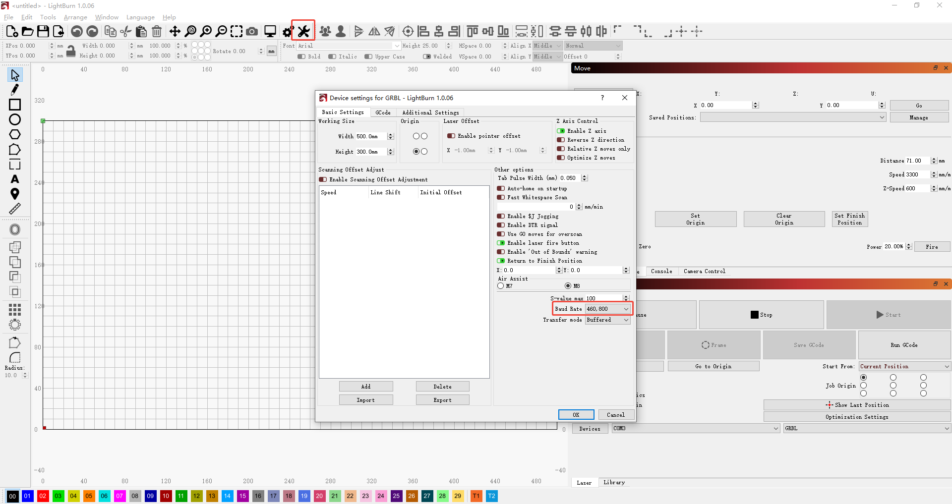
Figure 3
¶ Mobile App Connection
Please refer to the K2 Pro Mobile App Connection Video for detailed instructions.
Operation Steps
1. Install the App
Search for “AtomStack” in your mobile app store, then download and install the app.
2. Connect the Device
① Press and hold the “Wi-Fi” button for more than 5 seconds to enter Wi-Fi configuration mode.
② Open the app and tap “Add Device” on the home page. Follow the on-screen instructions to complete the device connection.
3. Requirements for Use
- Before using the app for engraving or cutting, make sure that a USB flash drive is inserted into the machine.
- The included 4 GB USB flash drive or another 8 GB USB flash drive is recommended. A capacity of more than 16 GB is not recommended to ensure normal data reading and writing by the machine.
- When configuring the device's Wi-Fi connection, the router must support the 2.4 GHz Wi-Fi band. The 5 GHz Wi-Fi band is currently not supported.
¶ Laser Focusing Guide
Please refer to the K2 Pro Laser Focusing Tutorial Video for detailed instructions.
The engraver supports two focusing methods: automatic focusing and manual focusing. The optimal focal distance is 40 mm.
1. Automatic Focusing
After placing the material, move the laser module directly above the material. Press the “AUTO FOCUS” button on the enclosure or click the “Auto Focus” button in the software to complete the focusing process.
Note:
- Soft or thin materials, such as felt and fabric, cannot be used with automatic focusing. Please use manual focusing instead.
- AtomStack Studio: An “AF” button is located next to the directional controls. Click the “AF” button to start automatic focusing.
- LightBurn: After importing the configuration file, an automatic focusing macro button labeled “Focus” will be added, as shown in Figure 4. Click the “Focus” button to start automatic focusing. You can also enter the
[ESP500]command in the Console to perform automatic focusing
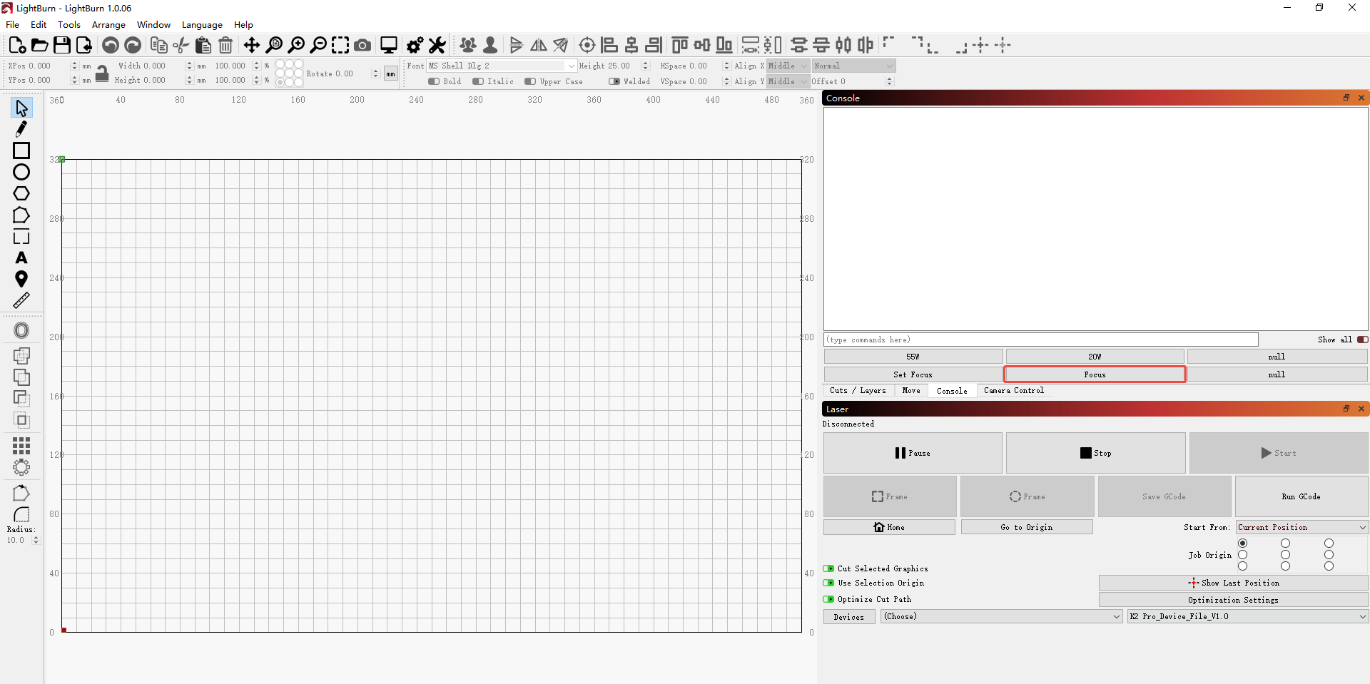
Figure 4
2. Manual Focusing
After placing the material, move the laser module directly above the material. Place the included focus piece (Ø15 × 40 mm) between the material and the laser module.
Use the manual adjustment knob at the rear bottom of the Z-axis, as shown in Figure 5, to adjust the Z-axis height. Continue adjusting until the bottom of the laser module just touches the focus spacer. Fix the Z-axis at this height, then remove the focus piece.
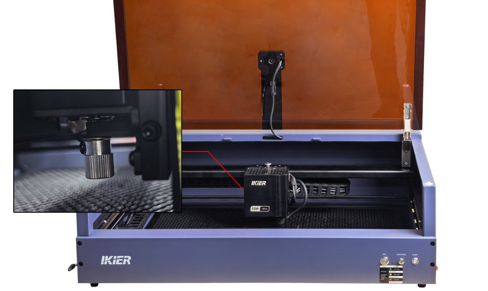
Figure 5
¶ Laser Module Replacement Guide
Please refer to the K2 Pro Laser Module Replacement Video for detailed instructions.
1. Removal
① Turn Off the Power
Before removing the laser module, turn off the engraver to ensure safe operation.
② Disconnect All Laser Module Connections
Gently pull out the side cable and bottom air assist hose in the direction of the connectors. Do not pull forcefully to prevent loose cable connectors, damaged hoses, or broken internal wires.
③ Loosen the Laser Module
Unscrew the knurled screw on the top of the laser module. Keep the module steady during removal to avoid damaging the threads.
④ Remove the Laser Module
Support the laser module securely with both hands and carefully remove it. Place it on a clean, ESD-safe work surface to prevent impact or other damage.
2. Installation
① Install the Laser Module
- Align the new laser module with the mounting slot on the Z-axis and lower it into position from above. Make sure the two grooves on the back of the laser module are fully engaged with the support posts on the Z-axis, with no looseness or misalignment.
- Keep the laser module flush against the Z-axis. Align the hole in the mounting slider precisely with the screw hole on the Z-axis, then tighten the knurled screw.
② Reconnect the Cables and Hose
- Reconnect the laser module cable and air assist hose. Pay close attention to the connector orientation and make sure the connectors are properly aligned before inserting them. Do not insert them in the wrong direction, as this may damage the equipment.
- Push the air assist hose firmly into place to ensure a secure seal and prevent air leakage.
3. Precautions
After installation, do not turn on the power immediately. First check that all connections are secure, all screws are properly tightened, and the hose is free of air leaks. Only turn on the machine for testing after confirming that everything is properly installed.
¶ Camera Usage Guide
Refer to the K2 Pro Camera Usage Tutorial Video for operation instructions. The following provides standardized written instructions.
1. Connect the Device
When connecting the engraver to a computer, a Type-C data cable must be used. The camera function supports USB connection mode only and does not currently support Wi-Fi connection mode.
2. Software Operation
AtomStack Studio
When using AtomStack Studio, only camera alignment is required. Keep the inside of the enclosure well lit during the operation.
① Confirm the Connection Method
Open the software and confirm that the connection method displayed in the upper-right corner of the interface is set to USB Connection.
② Select Absolute Coordinates
When using the camera function, set the coordinate mode to Absolute coordinates.
③ Select the Camera
Click Camera, then select the correct camera name from the Camera name list. The camera settings interface will appear after the camera is selected.
④ Align the Camera
- Open the interface: Click Calibrate camera alignment to enter the camera alignment interface.
- Frame: At the bottom of the alignment interface, click Frame to frame the work area and ensure that the engraving object is within the engraving area.
- Set the parameters: Set the “Line” and “Fill” parameters according to the material being processed to ensure that the engraved pattern can be clearly recognized by the camera.
- Engrave: Click Start to begin engraving. Wait several minutes until the engraving is complete.
- Capture the image: After engraving is complete, the software will automatically switch to the “capture” interface. Click Capture to capture the image. Check the capture score. The score must be less than 3.0. A lower score indicates higher accuracy. If the score is too high, click “Capture” to capture the image again. If the score meets the requirement, click “Calibrate Complete” to complete the alignment.
- Take a photo: Click “Take Photo” on the navigation bar to capture an image of the workpiece.
Note: On devices with smaller displays, you may need to drag the navigation bar's scroll bar to the right to display the “Take Photo” button.
LightBurn
① Select Absolute Coordinates
When using the camera function, set the coordinate mode to “Absolute coordinates”.
② Enable Camera Control
Open the “Window” menu at the top of the interface and check “Camera Control”. The “Camera Control” option will then be available in the control console.
③ Select the Camera
In the “Camera” drop-down list in the “Camera Control” window, select the correct camera name, such as “USB Camera”.
④ Calibrate the Camera
- Open the interface: In the “Camera Control” window, right-click and select “Calibrate Camera Lens” to start the lens calibration process.
- Select the camera and lens: In the pop-up dialog box, select the correct camera name and “Standard Lens” type, then click “Next”.
- Capture the image: Disable the “Honeycomb check enabled” option. Place the dot pattern focus target at the exact center of the enclosure, as indicated by the image in the interface. Click “Capture” to capture the image. When complete, click “Next” to proceed.
- Continue capturing: Follow the on-screen instructions and capture images at the following eight positions in sequence: bottom, left, right, top, bottom-right, bottom-left, top-left, and top-right. After all captures are complete, click “Finish” to complete the calibration.
Notes:
- It is recommended to place kraft paper or plywood underneath the focus target to prevent recognition errors during image capture.
- Be sure to remove the focus target after calibration is complete.
- A capture score is displayed after each click of Capture. A higher score indicates more precise calibration.
⑤ Align the Camera
- Home the machine: Click “Home”.
- Open the interface: In the “Camera Control” window, right-click and select “Calibrate Camera Alignment” from the pop-up dialog box.
- Select the position: In the pop-up interface, select “Camera is over the work area, in a fixed position” and proceed to the next step.
- Select the camera: Under “Select your camera”, select “USB Camera”, then click “Next”.
- Set the parameters: Enter 150 for “Scale”. Enter 7000 for both “Fill Speed” and “Line Speed”. Enter 15 for both “Fill Power” and “Line Power”.
- Frame: Click “Frame” to frame the work area and ensure that the engraving object is within the engraving area. If it is outside the engraving area, adjust the position of the material.
- Start engraving: Click “Start” to begin engraving.
- Capture Image: After engraving is complete, use the direction keys at the bottom left of the interface to move the laser to a position where it does not block the view. Click “Capture Image” to capture the image. After confirming that the image is normal, click “Next” to proceed to the next step.
- Mark the points: Use the mouse wheel to zoom in on the image, then click the center points of patterns “1”, “2”, “3” and “4” in sequence as prompted. When complete, click “Next”.
Note: Zoom in on the patterns before selecting their center points. The more precisely the center points are selected, the higher the alignment accuracy.
- Complete the alignment: When the interface indicates that all steps have been completed, click “Finish” to complete the camera alignment.
- Take a photo: In the “Camera Control” window, click “Update Overlay” to capture the latest image of the workpiece.
¶ Conveyor Feeder Usage Guide
Refer to the K2 Pro Conveyor Feeder Usage Tutorial Video and follow the steps below.
1. Install the Conveyor Feeder
① Install the H4 Riser
Assemble the H4 Riser according to the video or user manual. After assembly, place it on a stable work surface.
Note: Leave at least 510 mm of clearance between the work surface and the wall as the operating space for the conveyor feeder.
② Assemble the Conveyor Feeder
Assemble the R7 Conveyor Feeder according to the video or user manual.
Notes:
- When installing the R7 Conveyor Feeder, pay attention to the orientation of the sliding platform. Do not install it in the reverse direction, as this may cause the screws to rub against the aluminum profiles.
- If the platform slides too tightly or too loosely, adjust it using the three eccentric nuts on the bottom, as shown in Figure 6.
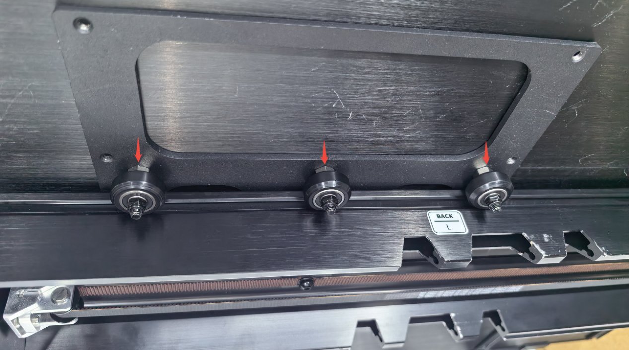
Figure 6
③ Install the Conveyor Feeder
Place the assembled conveyor feeder into the recessed area of the H4 Riser, ensuring that the mounting blocks on the conveyor feeder are inserted into the positioning holes on the H4 Riser, as shown in Figure 7.
Conveyor Feeder Orientation: The USB port should be located at the front-left side of the engraver.
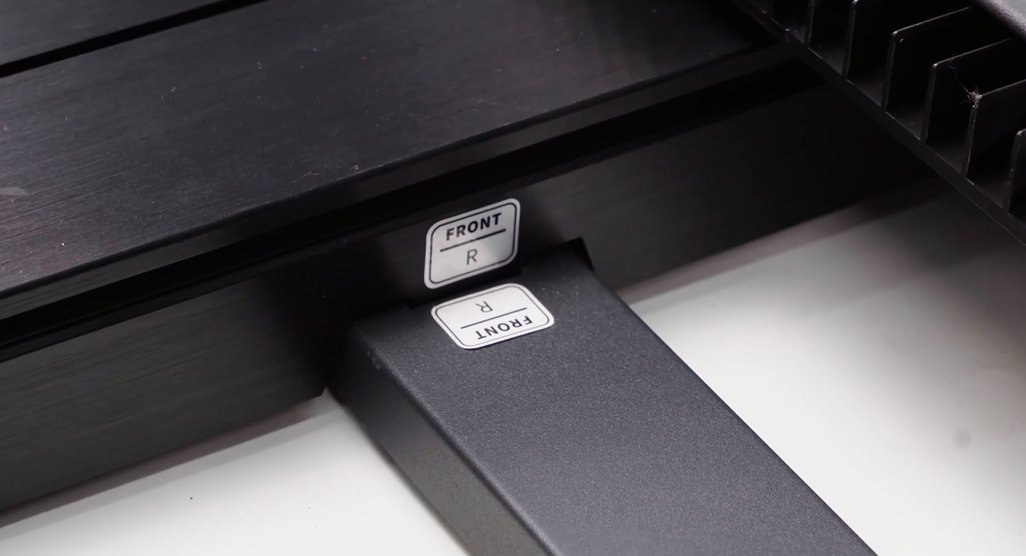
Figure 7
2. Remove the Honeycomb Bed
Open the enclosure door and push the laser module to the innermost position. Remove the honeycomb bed diagonally from the side of the door frame closest to the operator.
3. Remove the Bottom Plate
Turn the engraver over or place it upright. Use the L2.0 hex key to remove the 18 screws on the bottom of the machine, then remove the bottom plate.
Note: After the bottom plate is removed, the engraver no longer complies with the Class 1 laser product safety classification under IEC 60825-1 and is classified as a Class 4 laser product. Always wear appropriate laser safety glasses before operating the engraver again.
4. Place the Engraver
Place the engraver on the H4 Riser, ensuring that the support feet of the engraver are inserted into the corresponding holes on the H4 Riser.
5. Connect the Conveyor Feeder
Use the supplied USB cable, as shown in Figure 8, to connect the automatic identification port on the conveyor feeder to the “ACCESSORY” port on the engraver.
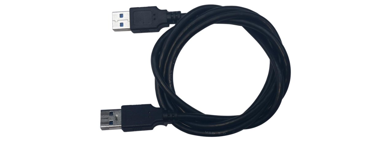
Figure 8
6. Software Settings
AtomStack Studio
When using AtomStack Studio, the system will automatically detect the connected R7 Conveyor Feeder. Click “OK” in the pop-up dialog box. No additional settings are required.
LightBurn
① Set the Engraving Area
Open the “Device Settings” window. Under “Working Size”, set the engraving area to 500 mm × 800 mm, as shown in Figure 9. Click “OK” to complete the setting.
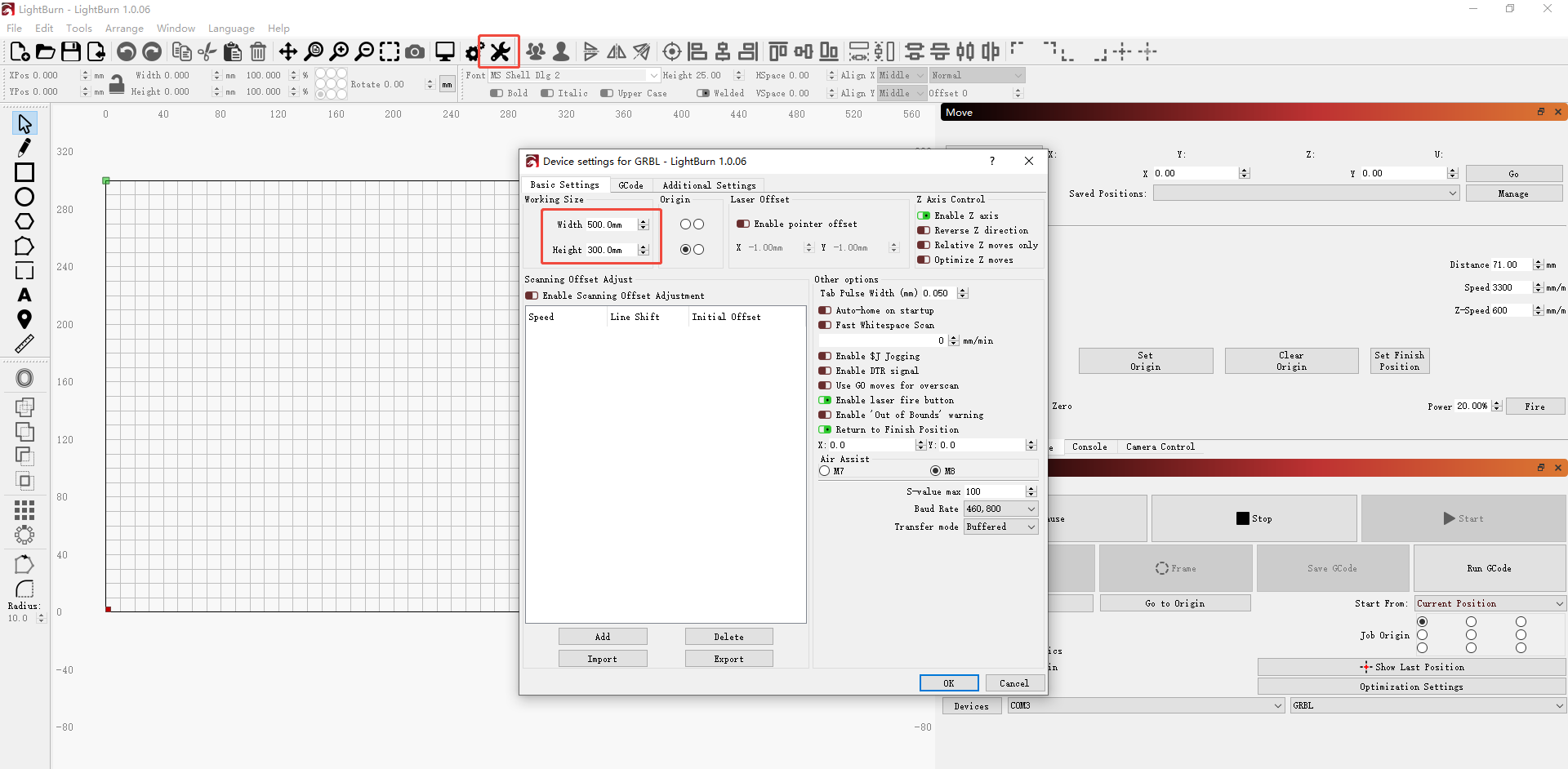
Figure 9
② Home the Machine
Click “Home”. The conveyor feeder will move upward.
③ Select the Coordinate Mode
- Current Position: Manually move the laser module to the starting position on the material, then click Frame to check whether the processing area is within the available engraving area.
- Absolute Coordinates: Processing can start at any position along the X-axis. However, the current X-axis position may affect the available engraving area.
¶ Rotary Attachment Usage Guide
Refer to the K2 Pro Rotary Attachment Usage Tutorial Video and follow the steps below.
1. Assemble the Rotary Attachment
① R6 Assembly
- After unpacking the R6 Rotary Attachment, refer to the user manual to check that all accessories are included and install the tail support.
- If the diameter of the workpiece is smaller than the gap between the two rollers, remove the fixing screws on the back of the rollers and adjust the roller support blocks to reduce the gap.
Note: For detailed instructions on adjusting the rollers, refer to the “How to Use” section of the user manual.
② R8 Assembly
- After unpacking the R8 Rotary Attachment, refer to the user manual to check that all accessories are included and install the tail support.
- Select a suitable chuck according to the type of material being processed. Refer to the user manual for details.
2. Install the H4 Riser
Assemble the H4 Riser according to the video or user manual. After assembly, place it on a stable work surface.
3. Remove the Honeycomb Bed
Open the enclosure door and push the laser module to the innermost position. Remove the honeycomb bed diagonally from the side of the door frame closest to the operator.
4. Remove the Bottom Plate
Turn the engraver over or place it upright. Use the L2.0 hex key to remove the 18 screws on the bottom of the machine, then remove the bottom plate.
Note: After the bottom plate is removed, the engraver no longer complies with the Class 1 laser product safety classification under IEC 60825-1 and is classified as a Class 4 laser product. Always wear appropriate laser safety glasses before operating the engraver again.
5. Place the Engraver
Place the engraver on the H4 Riser, ensuring that the support feet of the engraver are inserted into the corresponding holes on the H4 Riser.
6. Connect the Rotary Attachment
Use the supplied USB cable, as shown in Figure 10, to connect the automatic identification port on the rotary attachment to the “ACCESSORY” port on the engraver.
Figure 10
7. Software Settings
① AtomStack Studio
- Roller (R6): No parameter settings are required.
- Chuck (R8): Set the circumference or diameter of the material, as shown in Figure 11.
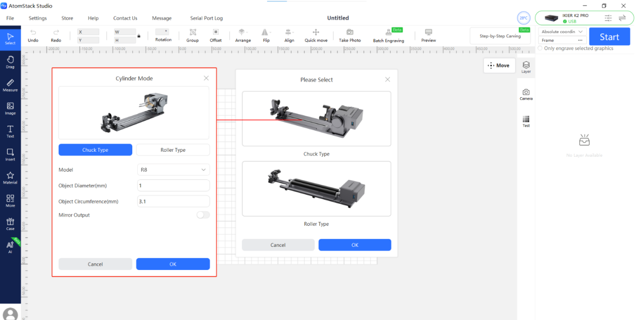
Figure 11
② LightBurn
Click “Tools” in the software menu bar and select “Rotary Setup” to open the rotary settings interface. Configure the following parameters:
- Rotary Type: Select “Roller” for R6 and “Chuck” for R8.
- Rotary Axis: Select the “Y-axis”.
- Rotary Circumference: Set R8 to 160 mm per revolution (fixed value) and R6 to 50 mm per revolution (fixed value).
- Rotary Diameter: This option is not available for R8. For R6, set the diameter to 16 mm (fixed value).
- Material Diameter/Circumference: Enter either the material diameter or circumference.
- Reference: See Figure 12.
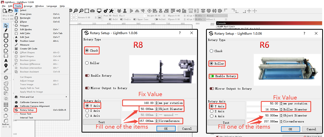
Figure 12
8. Important Notes When Using the R8 Chuck
- When using the R8 chuck, the maximum clamping diameter for cylindrical objects is 80 mm (range: 0–80 mm).
- When using the R8 chuck, the maximum clamping diameter for spherical objects is 80 mm (range: 25–80 mm).
- When using the R8 chuck, the maximum clamping diameter for round objects is 70 mm (range: 10–70 mm).
- When using the R8 chuck, the maximum load capacity is 1.5 kg.
¶ Air Assist Usage Guide (with Fire-Extinguishing Function)
Refer to the K2 Pro Air Assist Usage Tutorial Video and follow the steps below.
1. Connect the Devices
① Connect the Air Assist Cable
Take the cable with the yellow label and connect it to the “AIR ASSIST” port on the air assist system and the “AIR ASSIST” port on the engraver.
② Connect the Fire Safety Cable
Take the cable with the white label and connect it to the “FIRE SAFETY” port on the air assist system and the “FIRE SAFETY” port on the engraver.
③ Connect the Silicone Hose
Take the silicone hose and connect it to the “AIR TUBE” port on the air assist system and the “AIR TUBE” port on the engraver.
Note: The cables feature a keyed design to prevent incorrect connections. If a cable is connected to the wrong port, it cannot be inserted. Do not force the connector into the port.
2. Add Water to the Water Tank
Open the water tank cover, as shown in Figure 13, and add an appropriate amount of purified water or distilled water.
Observe the water level indicator. The water level must be above the minimum “L” mark and must not exceed the maximum “H” mark.
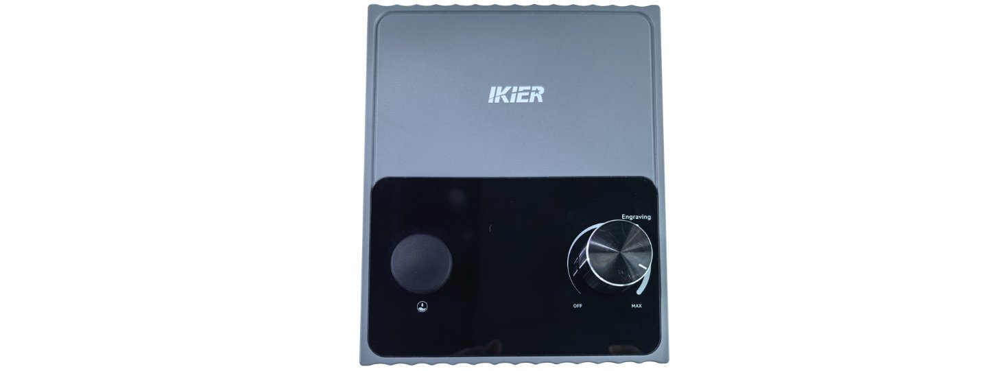
Figure 13
3. Automatic Fire Extinguishing
- Trigger Condition: The flame alarm is triggered during processing.
- Fire-Extinguishing Action: The Z-axis automatically moves to its highest position, and the nozzle continuously sprays water for 5 seconds within the 30 mm × 30 mm alarm detection area. After spraying stops, the air pump continues blowing air for approximately 1 minute to dry the inside of the air duct cover.
Note: The 1-minute air blowing period is intended to remove residual water from inside the hose and nozzle. If water droplets remain after 1 minute, you can continue running the air assist system for another 5 minutes.
¶ Batch Engraving Software Usage Guide
Refer to the K2 Pro Batch Engraving Software Usage Tutorial Video and follow the steps below.
Note: Camera-based image capture involves a certain degree of error. If high-precision engraving is required for every workpiece, the Batch Engraving function is not recommended.
1. Connect to AtomStack Studio
Connect to the AtomStack Studio client according to the Computer Connection section.
2. Calibrate the Camera
If camera alignment has already been completed, skip this step.
If the camera has not yet been aligned, first complete the calibration according to the Camera Usage Guide section.
3. Place the Materials
Place the materials to be batch engraved within the engraving area of the enclosure. After positioning all materials, close the enclosure door.
4. Capture the Image
Click “Capture” in the software menu bar to capture an image of the materials.
5. Import the Engraving File
Drag the file to be engraved onto one of the workpieces, then adjust its size, position, and processing parameters as required.
6. Batch Fill
Click “Batch Engraving” in the software menu bar. In the pop-up interface, click “Fill” and wait for the software to automatically place the engraving file onto all workpieces.
7. Frame and Engrave
Select all engraving files and click Frame to check whether the engraving area meets the requirements.
If there are no issues, click “Start” in the upper-right corner to begin engraving.
¶ Software Coordinate System Overview
- Current Position: Uses the current position of the laser module as the engraving starting point. You can manually move the laser module to any desired engraving position.
- User Origin: Uses the position manually set by the user as the starting point for laser processing.
- Absolute Coordinates: Uses the 0,0 position after homing as the origin and uses the coordinates of the processing file as the starting position for the laser.