¶ Master Troubleshooting
Step-by-step checks for power, connectivity, camera, optical path, motion, focus, and alarm issues.
¶ Master Troubleshooting Quick Reference
¶ Master Cannot Power On Normally, and the Power Indicator Light Is Off

Solution: Please refer to the Master power-on troubleshooting video.
- Check the voltage specification:
Make sure the machine matches the local mains voltage. Master is available in both 220V and 110V versions for different regional power standards.
- Check the power cable:
Make sure the power cable is securely connected. Unplug the power cable and reconnect it firmly.
- Check the emergency stop switch:
Make sure the emergency stop switch has been released. Press the knob, rotate it clockwise, and then release it.
- If the issue still cannot be resolved, the power switch may be faulty. Please provide a photo of the machine’s Serial Number (see Figure 20) and a video showing the issue to customer service for assistance.

For power switch replacement instructions, please refer to the Master power switch replacement video.
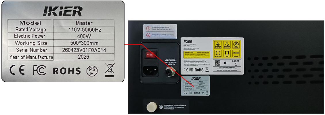
Figure 20
¶ Master Cannot Power On Normally, but the Power Indicator Light Is On
Solution: Please refer to the Master power-on troubleshooting video.
- Check whether there is a buzzer sound after powering on:
If there is no buzzer sound, it indicates that the mainboard has not started properly. First, check whether the indicator light on the mainboard is on.
- Check the mainboard indicator light:
- If the mainboard indicator light is on, but there is no buzzer sound and the machine cannot connect normally:
This may indicate a mainboard failure. Disconnect all cables connected to the mainboard except for the mainboard power cable (see Figure 21), then restart the machine to check whether the buzzer sound can be heard and whether the machine can connect properly.
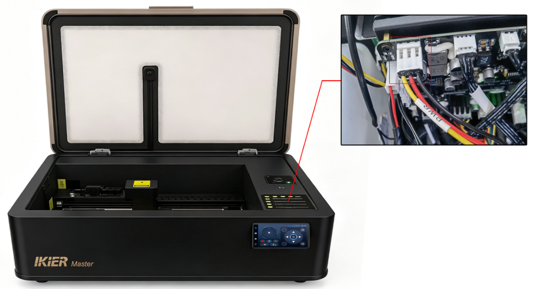
Figure 21
-
If the machine starts normally and connects properly after disconnecting the other cables, reconnect the cables one by one to identify which cable is causing the issue, then report the results to customer service for assistance.
-
If there is still no buzzer sound, the mainboard is likely faulty. Please send the machine’s Serial Number and a video showing the issue to customer service for assistance. For mainboard replacement instructions, please refer to the Master mainboard replacement video.
-
If the mainboard indicator light is not on:
This may indicate a switching power supply failure. If you have a multimeter, use the DC voltage mode to measure whether the input voltage between the red and black wires of the mainboard power cable is 24V (see Figure 22).
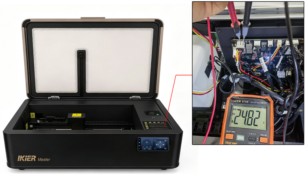
Figure 22
-
If no voltage is detected, the switching power supply is considered faulty. Please send the machine’s Serial Number (see Figure 23) and a video of the voltage measurement to customer service for assistance. For switching power supply replacement instructions, please refer to the Master switching power supply replacement video.
-
If 24V is measured but the mainboard appears to be continuously restarting, the switching power supply may still be faulty.
Figure 23
¶ Master Cannot Connect to the Computer

Solution: Please refer to the Master connection troubleshooting video.
- Confirm that the machine has started normally:
Check whether you can hear the mainboard buzzer sound.
-
If the buzzer sound is heard, the machine has started normally.
-
If there is no buzzer sound, please refer to the “Master Cannot Power On Normally” section for troubleshooting.
- Check whether the Type-C cable is properly connected:
Disconnect the Type-C cable from both ends and reconnect it to the machine and the computer USB port, or try a different USB port on the computer.
- Confirm the operating system:
-
Windows computers can directly use a Type-C to USB-A cable or a USB-C connection.
-
macOS or HarmonyOS computers require a docking station/hub (see Figure 24) to connect the USB-A end of the Type-C cable.
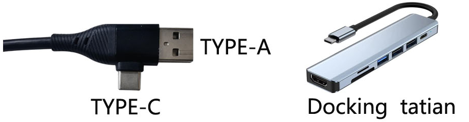
Figure 24
- Check the serial port:
-
When using AtomStack Studio, no additional confirmation is required.
-
When using LightBurn, make sure the correct serial port is selected. Check which COM port the CH340 device is assigned to in the computer’s Device Manager (see Figure 25).
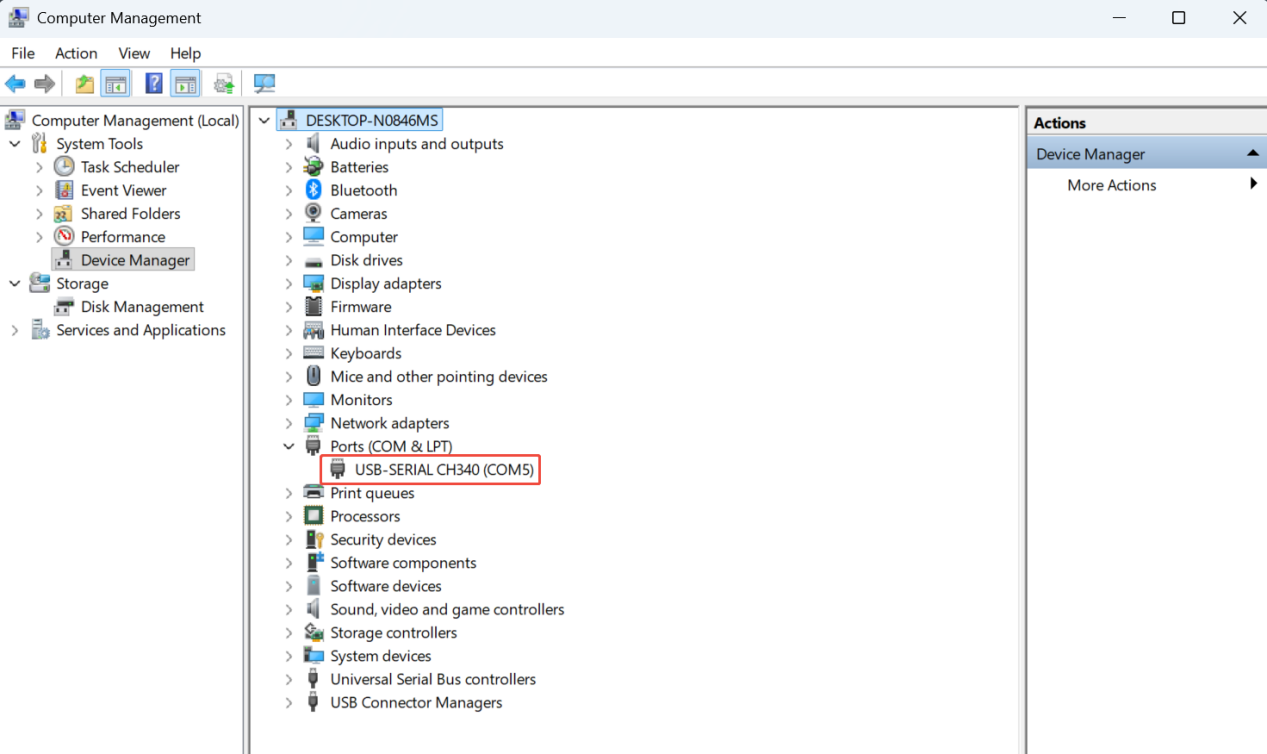
Figure 25
- Make sure no other software is occupying the connection:
Ensure that no other software is currently connected to the engraving machine.
- Check the configured controller:
- AtomStack Studio does not require additional setup.

- When using LightBurn, make sure a GRBL controller has been added or import the factory configuration file included with the Master. Please refer to the LightBurn connection section in the Master online connection tutorial video.
Check the serial port driver:
In Device Manager, check whether a CH340 serial device is present. If not, please install the serial driver first. Driver download links are as follows:
-
-Windows driver download link: https://asa.atomstack.com/downloadWindowsDrivers.do3
-
-Mac driver download link: https://asa.atomstack.com/downloadMacDrivers.do3
- Check the baud rate:
-
AtomStack Studio does not require this setting to be checked.
-
When using LightBurn, make sure the baud rate is set to 460800 (see Figure 26).
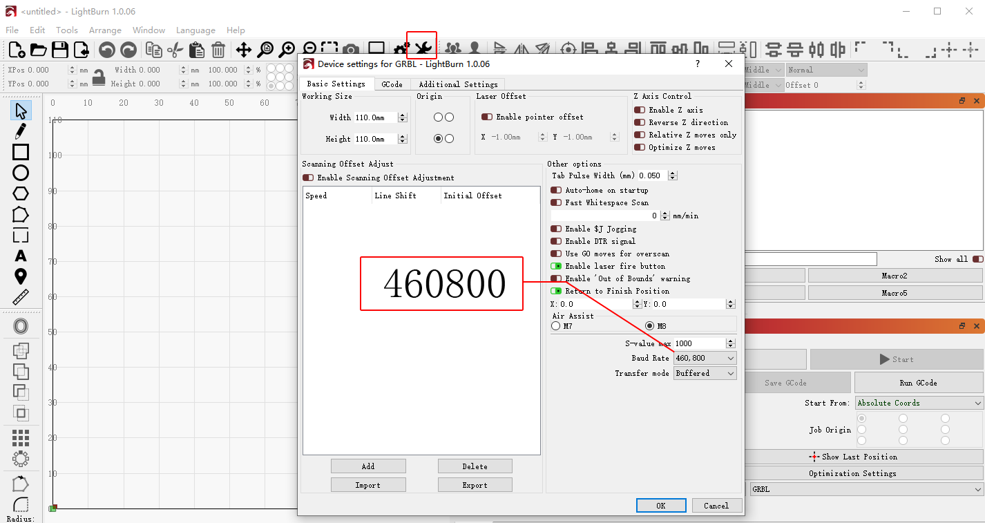
Figure 26
- Check the computer and software:
If possible, try connecting the machine using another computer to determine whether the connection works properly.
- If the issue still cannot be resolved after completing the above steps, please send a video showing the issue, the troubleshooting steps already performed, and the machine’s Serial Number (see Figure 27) to customer service for assistance.
Figure 27

For mainboard replacement instructions, please refer to the Master mainboard replacement video.
¶ Master’s Control Screen Has No Display After Powering On
- Confirm that the machine powers on normally:
Make sure you can hear the mainboard buzzer sound during startup and that the machine can be controlled normally when connected to a computer.
If the machine does not start properly, please refer to the “Master Cannot Power On Normally” section.
-
Check the status of the control panel: Carefully inspect whether the control panel has been damaged during transportation.
-
Check the mainboard cable connections:
Open the internal cover panel of the enclosure and check whether the control screen cable is loose (see Figure 28).
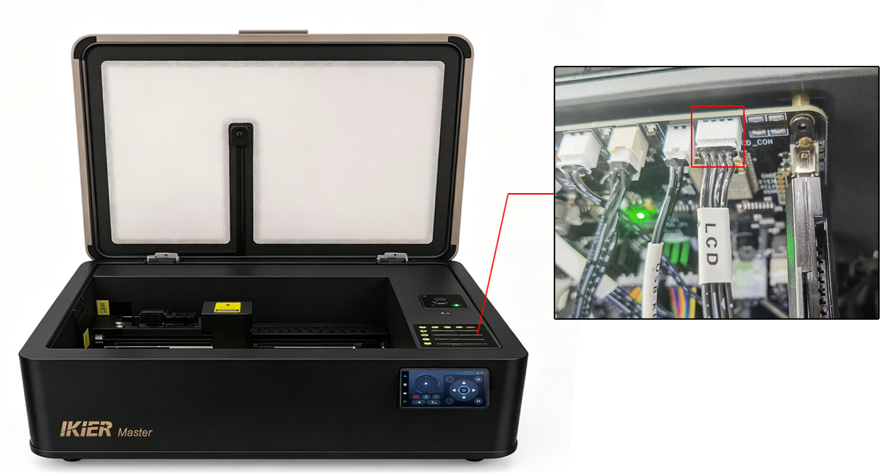
Figure 28
- Check the mainboard firmware version:
After connecting the machine, check the current firmware version in AtomStack Studio and send a screenshot to customer service so they can verify whether the firmware version is correct (see Figure 29).
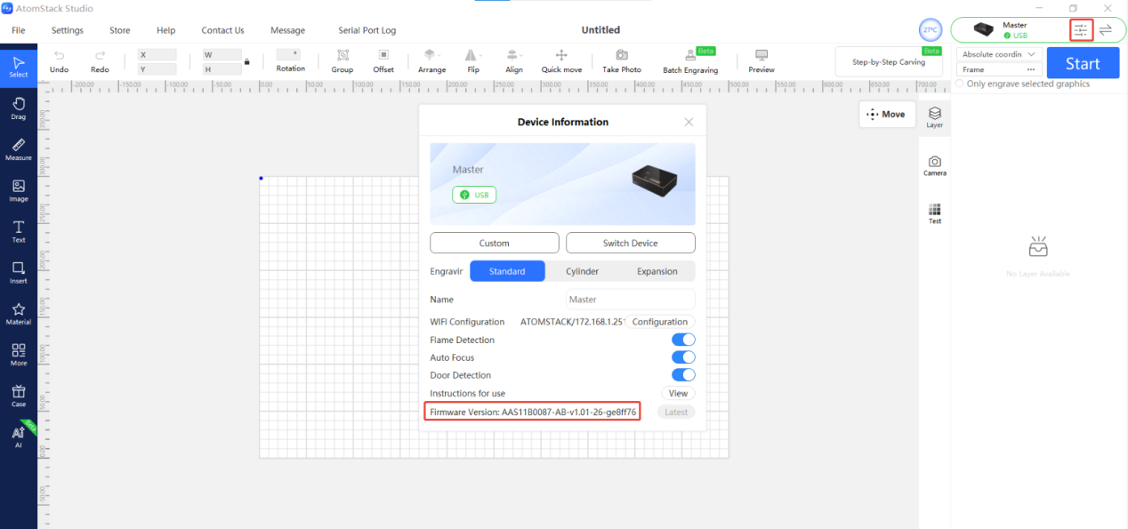
Figure 29
- If no issues are found after completing the above checks, the control screen may be faulty. Please send a video showing the issue, the troubleshooting steps already performed, and the machine’s Serial Number (see Figure 30) to customer service for assistance.
Figure 30

For control screen replacement instructions, please refer to the Master control screen replacement video.
¶ Camera of Master Cannot Be Used
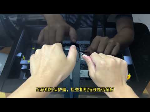
Solution: Please refer to the Master camera troubleshooting video.
- Check the coordinate mode selected in the software:
When using the camera, Absolute Coordinates mode must be enabled.
- Check whether the camera is disabled:
Open Device Manager and check whether the camera has been restricted or disabled. Make sure the necessary permissions are enabled and access is allowed (see Figure 31).
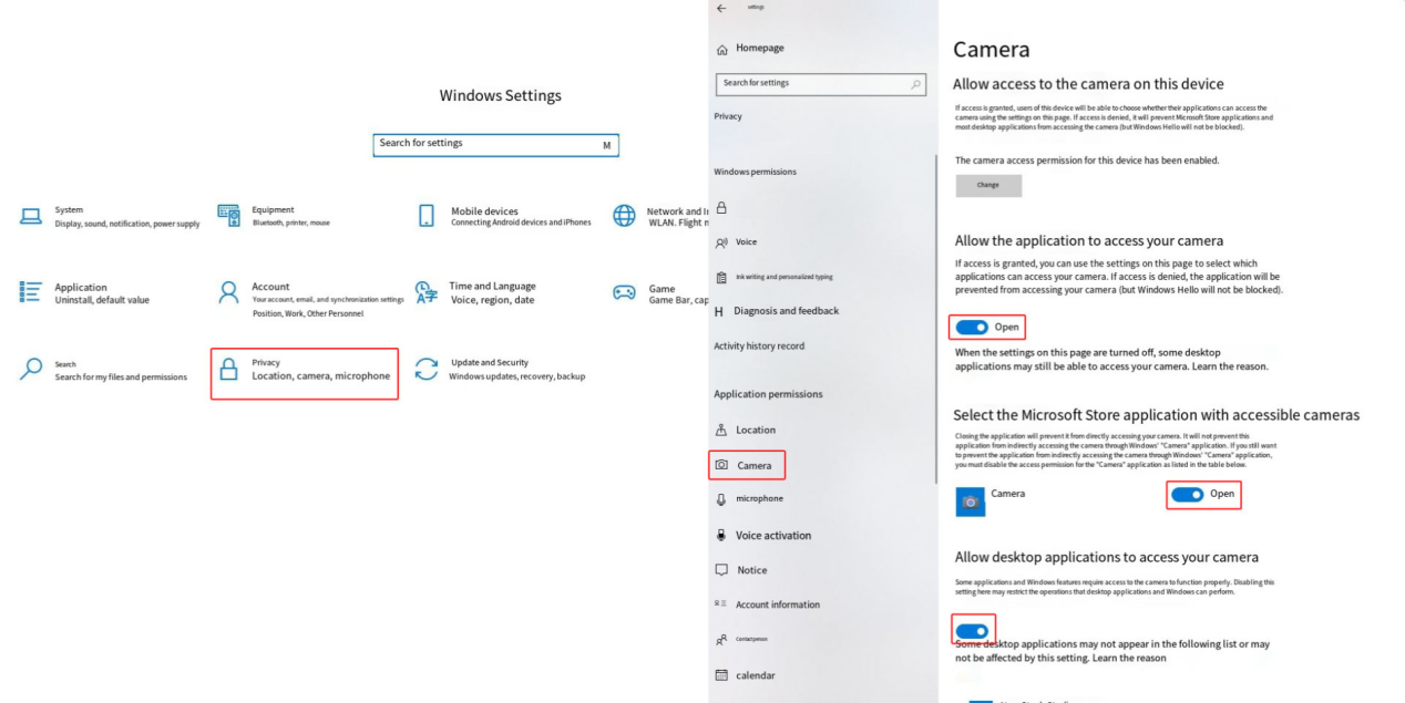
Figure 31
- Check whether the computer USB port is faulty:
Try connecting to a different USB port on the computer, and use the computer’s built-in camera application to check whether the camera outputs an image (see Figure 32).
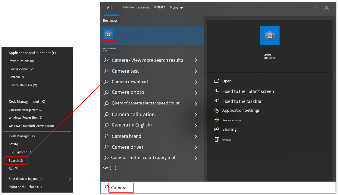
Figure 32
- Check whether the camera USB cable on the mainboard is loose:
If no image is displayed, check whether the camera USB cable connected to the mainboard is loose (see Figure 33). Disconnect and reconnect the cable, then test the camera function again.
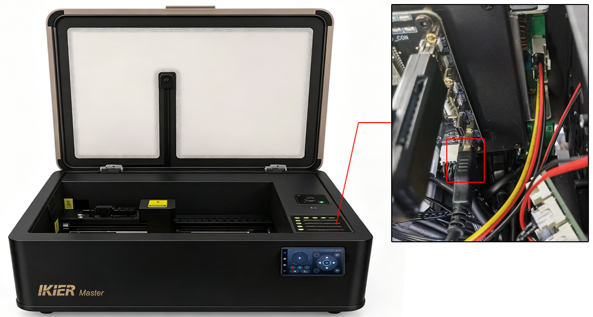
Figure 33
- Check whether the camera cable connection is loose:
Use a flat-head screwdriver to pry open the camera protective cover (see Figure 34), then check whether the cable connector is loose.
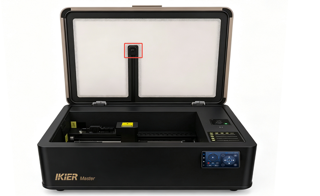
Figure 34
- If the above steps do not resolve the issue and the computer’s built-in camera application still cannot display an image, please send a video showing the issue, the troubleshooting steps already performed, and the machine’s Serial Number (see Figure 35) to customer service for assistance.

For camera replacement instructions, please refer to the Master camera replacement video.
Figure 35
¶ Master’s Camera Positioning Is Inaccurate or Has Large Errors
- Check the coordinate mode selected in the software:
When using the camera, Absolute Coordinates mode must be enabled.
- Confirm that calibration has been completed:
- When using AtomStack Studio, only alignment is required.

- When using LightBurn, follow the instructions in the manual and complete the calibration step by step according to the software prompts. Please refer to the Master camera operation video for calibration guidance.
Note: LightBurn version 1.7.03 or later is recommended, as it provides easier operation and higher calibration accuracy.
- Make sure the interior lighting is bright enough:
The enclosure lighting brightness can be adjusted from the control screen. When using the camera, set the lighting brightness to the maximum level (see Figure 36).
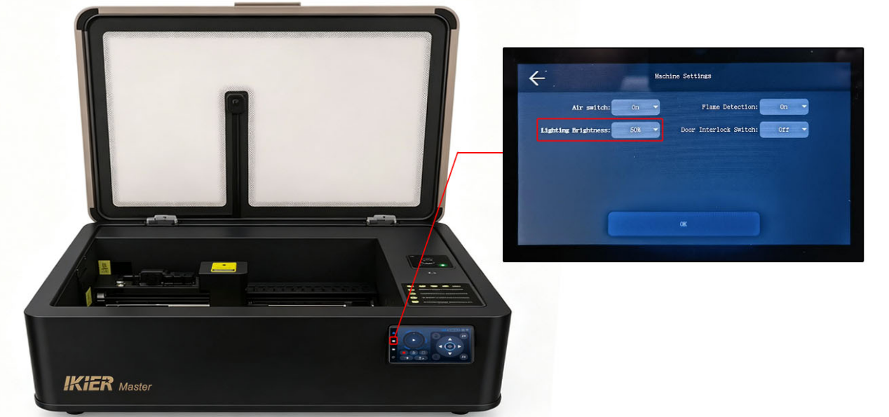
Figure 36
- Make sure the air pump is turned off:
During camera calibration, disable the air assist/air pump function from the control screen (see Figure 37).
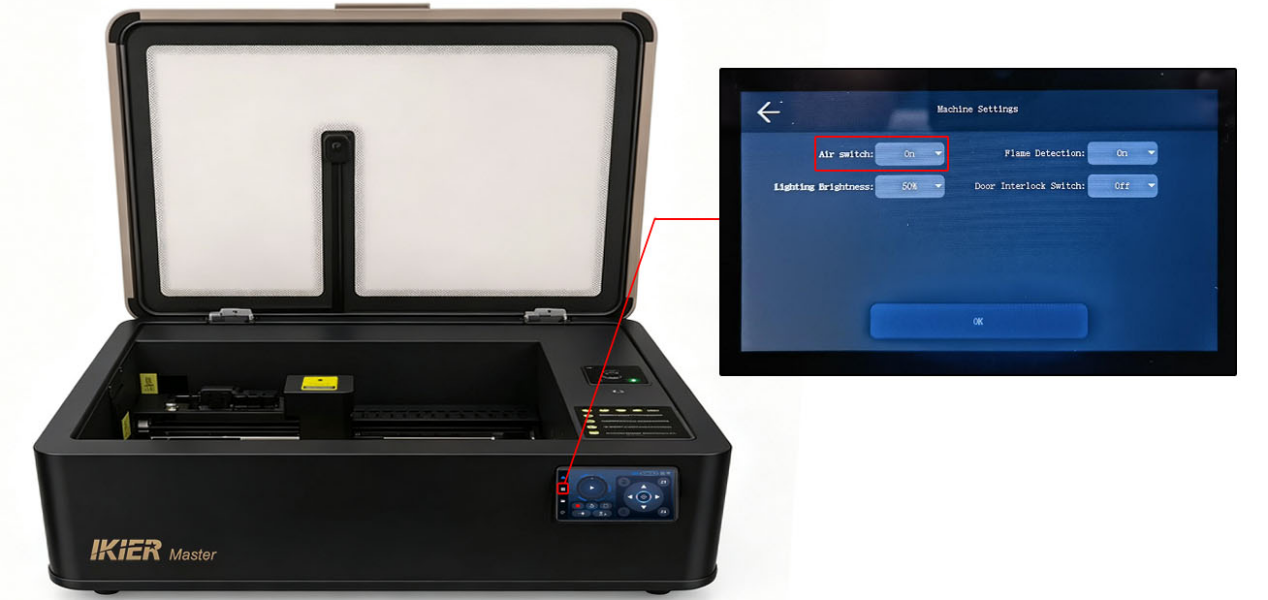
Figure 37
- Check the material height:
The height used during calibration should match, or be very close to, the height of the actual engraving material. If the material height differs significantly from the calibration height, recalibration is required.
- Check the calibration tool:
Kraft paper is recommended for alignment, although plywood may also be used. The calibration piece should be flat and have clear, easily distinguishable lines.
- Confirm operational details:
If lightweight pieces such as kraft paper are used during calibration, make sure they are securely fixed in place to prevent movement during engraving.
¶ The Master CO₂ Laser Power Is Abnormal and Cannot Fully Cut Through Materials

Solution: Please refer to the Master laser power troubleshooting video.
- Check the reflective mirrors:
With the machine powered off, remove and inspect Mirrors #1, #2, and #3 to check whether they are clean (see Figure 38). If they are dirty, clean them using anhydrous ethanol and a lint-free cloth. Please refer to the “Master Reflective Mirror Cleaning” section for cleaning instructions.
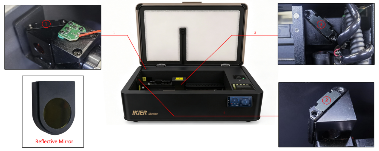
Figure 38
- Check whether the red guide laser dot overlaps with the laser burn spot:
Attach a piece of masking tape or white paper to the focusing lens frame. Press the Laser Test button on the control screen or in the software to briefly fire the laser, then check whether the burn mark overlaps with the red guide laser dot.
If they do not overlap, open the internal shield panel and adjust the beam combiner module screws located in front of the CO₂ laser tube (see Figure 39) until the red guide dot and burn mark align.
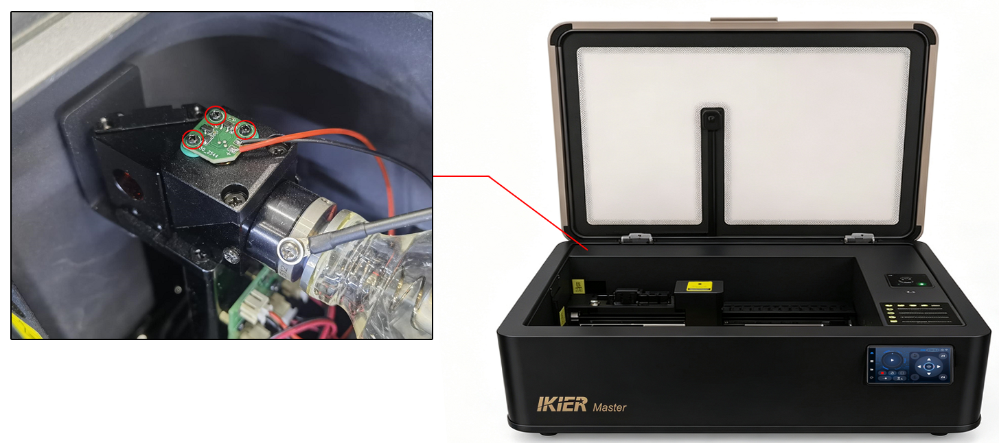
Figure 39
- Check the red guide laser position in the optical path:
With the machine powered on, attach a piece of masking tape or white paper to the third mirror (Z-axis mirror) and mark the current red guide laser position with a pen.
Then move the X-axis and Y-axis around the four inner edges of the enclosure and check whether the red guide laser position shifts relative to the marked point.

If the position shifts, the optical path must be realigned. Please refer to the Master optical path verification and calibration video.
- Check the cutting performance:
Cut a large square-shaped piece of material and check whether all sides are fully cut through.
If one side cuts through properly while another side does not, the optical path needs to be realigned.
- Check the focusing lens:
Remove the cover of the focusing lens tube and take out the focusing lens(see Figure 40). Check whether the focusing lens is damaged.
If it is only dirty, please refer to the “Master Focusing Lens Cleaning” section for cleaning instructions.
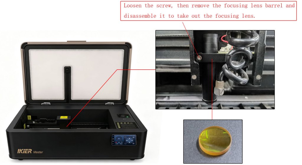
Figure 40
- If no issues are found after completing the above checks, please send the following information to customer service for assistance:
-
A video showing the optical path verification process
-
A cutting test video (clearly showing the software power settings, material type, and material thickness)
-
A photo of the machine’s Serial Number (see Figure 41)

For laser tube replacement instructions, please refer to the Master laser tube replacement video.
Figure 41
¶ The Master Engraving Output Is Blurry
- Check the focus distance:
The auto focus distance is 8 mm. Please confirm that the distance between the bottom of the Z-axis focusing lens tube and the material surface is 8 mm.
- Check the lenses and mirrors:
After powering off the machine, inspect Mirrors #1, #2, #3, and the focusing lens for dirt or contamination (see Figure 42). If necessary, please refer to the “Master Reflective Mirror Cleaning” and “Master Focusing Lens Cleaning” sections for cleaning instructions.
Figure 42
- Check whether the material has shifted:
If the engraving material is thin or lightweight, secure it properly to prevent movement during the engraving process.
¶ The Master Engraving Output Has Ghosting or Double Images
- Check the timing belts:
Press the X-axis and Y-axis timing belts by hand to check whether they are too loose or too tight. If adjustment is needed, use the belt tensioners located on the right side of the X-axis and the inner side of the Y-axis to adjust the belt tension (see Figure 43).
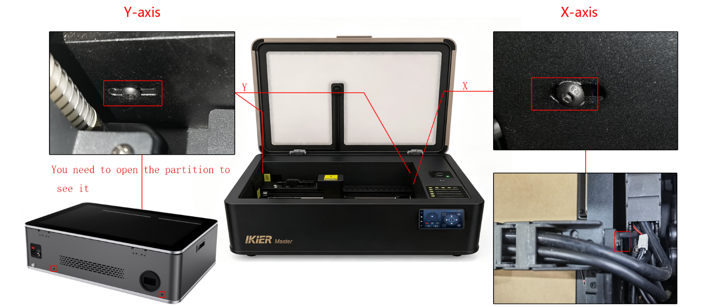
Figure 43
- Check the X/Y timing pulley screws:

To inspect the timing pulley screws, the outer cover and the X-axis motor mounting screws must first be removed. Please refer to the Master structural adjustment video.
- Check whether the X-axis is parallel to the upper and lower frame edges:
Use a ruler to measure whether the distances from both ends of the X-axis to the lower enclosure frame are equal.
If the distances are inconsistent, adjustment is required. Loosen the coupling screws on the Y-axis motor to make the adjustment. Please refer to the structural adjustment video.
- Check the software parameters:
Verify whether the engraving speed set in the software is too high. Please refer to the recommended parameter table. The speed unit is mm/min.
- Check whether the material has shifted:
If the engraving material is thin or lightweight, secure it properly to prevent movement during the engraving process.
¶ The Master Fails to Home Properly

Solution: Please refer to the Master homing failure troubleshooting video.
Check the homing process:
When the Reset/Home button is pressed, the machine follows this homing sequence:
① Home the Z-axis
② Move the Y-axis
③ Move the X-axis
Please identify at which step the issue occurs and observe the machine behavior. Troubleshoot according to the following steps.
- Check the motor status:
Use the directional buttons on the control screen (see Figure 44) to move the X-axis, Y-axis, and Z-axis motors and check whether they all operate normally.
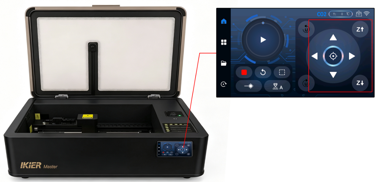
Figure 44
If a motor cannot move properly:
-
Disconnect the motor cable and reconnect it, then test again.
-
Note: Accessing the Y-axis motor requires removing the outer cover. If the Y-axis moves normally, this step is unnecessary.
If the issue persists, please send a video showing the issue, the troubleshooting steps already performed, and a photo of the machine’s Serial Number to customer service for assistance.

For motor replacement instructions, please refer to the Master motor replacement video.
- Check the limit switches:
Check the following limit switches one by one:
-
Z-axis upper limit switch
-
X-axis limit switches (2)
-
Y-axis limit switches (2)
Press each switch and check whether a corresponding trigger notification appears.
If no response is detected, please send a video showing the issue and a photo of the machine’s Serial Number to customer service for assistance.
- Check the machine firmware version:
After connecting through AtomStack Studio or LightBurn, check the firmware version (see Figure 45 and Figure 46).
Figure 45
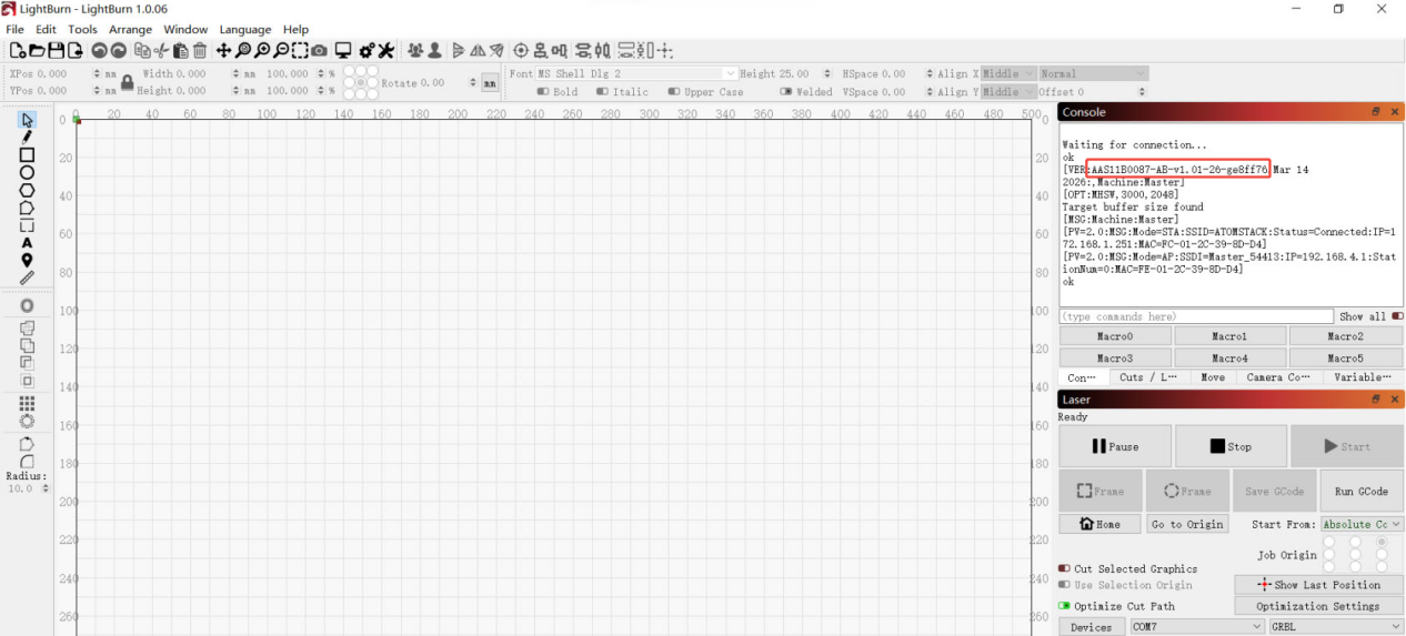
Figure 46
- If the issue still cannot be resolved after completing the above checks, please send the following information to customer service:
-
A video clearly showing the operation steps, machine movements, and any alarm messages
-
The troubleshooting steps already performed
-
A photo of the machine’s Serial Number (see Figure 47) 。
Figure 47
¶ The Master Engraving Output Is Distorted
Solution: Please refer to the Master structural adjustment section.
- Check the timing belts:
Press the X-axis and Y-axis timing belts by hand to check whether they are too loose or too tight. If adjustment is needed, use the belt tensioners located on the right side of the X-axis and the inner side of the Y-axis to adjust the belt tension (see Figure 48).
Figure 48
- Check the X/Y timing pulley screws:
To inspect the timing pulley screws, the outer cover and the X-axis motor mounting screws must first be removed. Please refer to the structural adjustment video.
- Check whether the X-axis is parallel to the upper and lower frame edges:
Use a ruler to measure whether the distances from both ends of the X-axis to the lower enclosure frame are equal.
If the distances are inconsistent, adjustment is required. Loosen the coupling screws on the Y-axis motor to make the adjustment. Please refer to the structural adjustment video.
- If the issue still cannot be resolved after completing the above checks, please send the following to customer service for assistance:
-
A video showing the X-axis parallelism measurement
-
A video showing the timing pulley screw inspection
-
A video showing the timing belt inspection
-
A photo of the machine’s Serial Number (see Figure 49).
Figure 49
¶ The Engraved Lines from Master Are Not Fully Closed

Solution: Please refer to the Master open-line troubleshooting section.
- Check the focus distance:
Measure the distance between the bottom of the Z-axis focusing assembly and the material surface to confirm that it is 8 mm.
If the distance is incorrect, refocus the machine. Please refer to the “Master Focus Distance Adjustment” section.
- Check the focusing lens:
Unscrew the focusing lens tube cover and remove the focusing lens to check for dirt or damage(see Figure 50).
If the lens is dirty, clean it using anhydrous ethanol and a lint-free cloth. Please refer to the “Master Focusing Lens Cleaning” section.
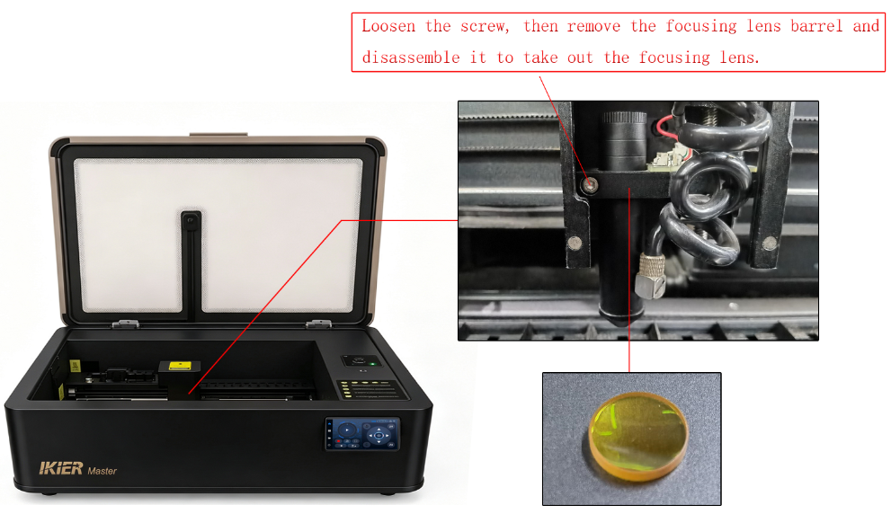
Figure 50
- Check the software parameter settings:
Use the recommended parameter settings for the corresponding material according to the parameter chart. Incorrect parameter settings may result in insufficient laser energy.
Note: The speed unit is mm/min.
How to access the Master parameter chart:
① Scan the QR code on the engraving machine to view it.
② Contact customer service to request the parameter chart.
- Check the laser optical path:
Perform verification and troubleshooting according to the “Master Optical Path Verification and Calibration” section.
- Enable Constant Power Mode:
Turn on the Constant Power function in the software and check whether the issue is resolved(see Figure 51).
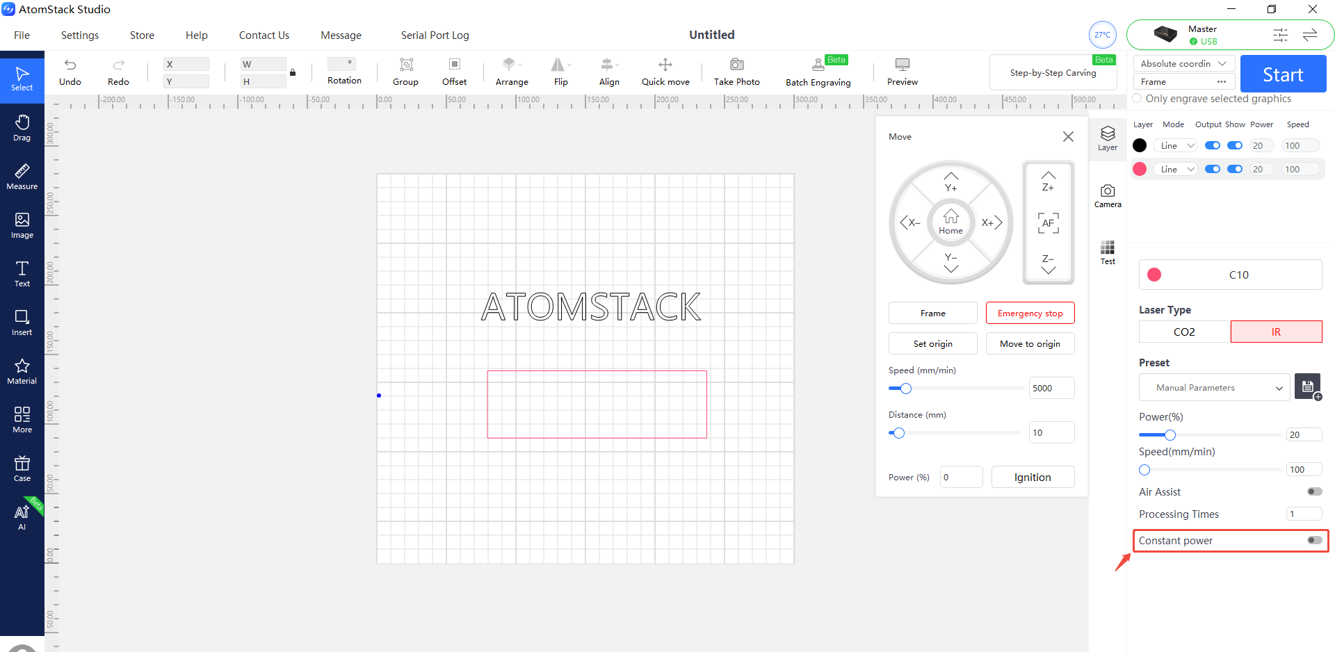
Figure 51
- Adjust the minimum power value ($31):
① In AtomStack Studio:
Open the Settings menu, then continuously left-click the software version field more than 7 times to enable the developer mode menu called “Serial Port Log.”
Open “Serial Port Log,” then enter the following command in the input field:
$31=*(see Figure 52)
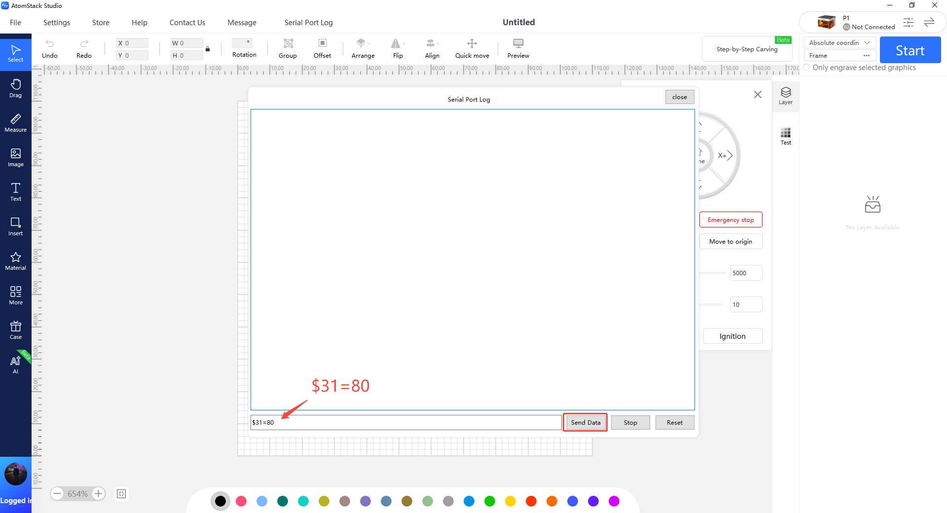
Figure 52
Replace * with a specific value and gradually increase it until the lines close properly.
For example:
If the lines do not close when $31=0, send:
$31=10
If the issue persists, continue increasing the value, for example:
$31=20
Repeat until the engraved lines close properly.
② In LightBurn:
Go to “Edit” → “Machine Settings,” then locate the $31 parameter.
Increase the value, click “Write,” then click “OK” to save the setting.
Repeat this process and continue increasing the $31 value until the lines close properly.
¶ Master Auto Focus Failure

Solution: Please refer to the Master auto focus troubleshooting guide.
- Confirm that the auto focus function is enabled:
After connecting the machine, check whether the auto focus function is enabled in the machine function settings page of AtomStack Studio (see Figure 53).
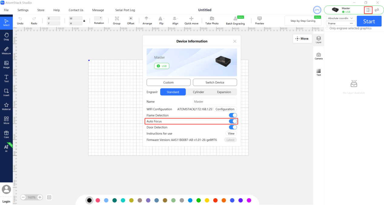
Figure 53
- Confirm that material is placed on the blade bed:
If no material is placed on the bed, the Z-axis may not be able to detect or contact the material properly, which can cause auto focus to fail.
- Confirm the material type:
If the material is soft or flexible, please use the Z-axis movement controls on the control screen to perform manual focusing instead. The focus distance should be 8 mm (see Figure 54).
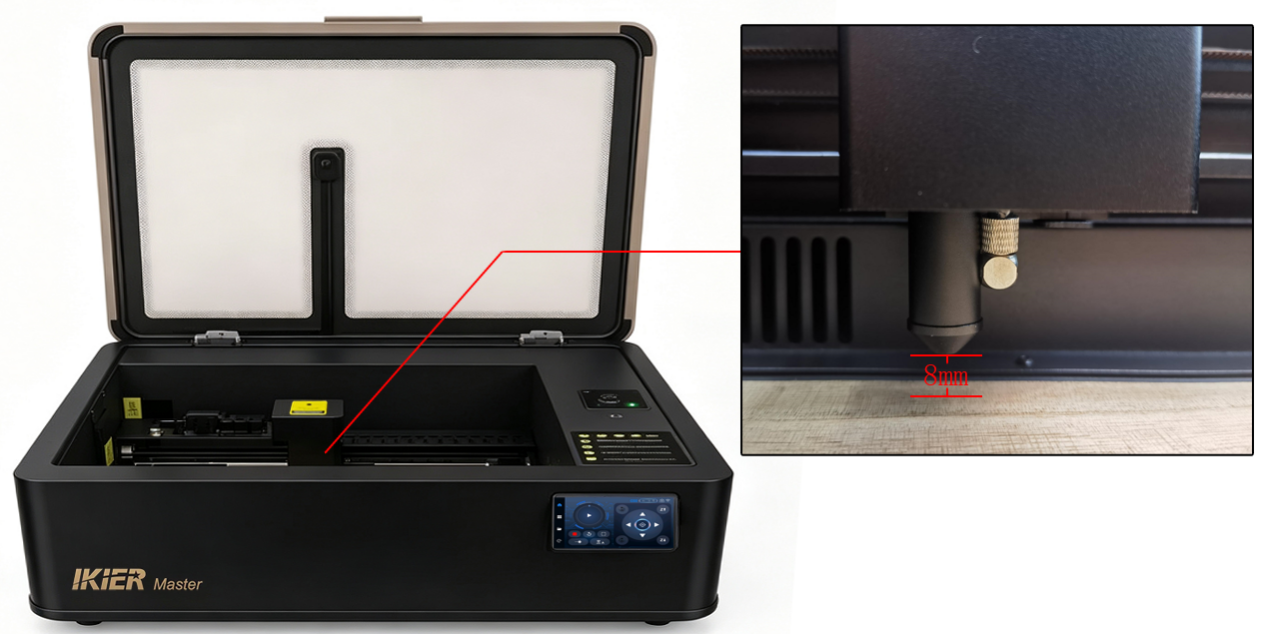
Figure 54
- Check the Z-axis upper and lower limit switches:
- Gently push the focusing lens tube upward by hand to check whether the lower limit switch can be triggered(see Figure 55). If it can be triggered, the lower limit switch is functioning normally.
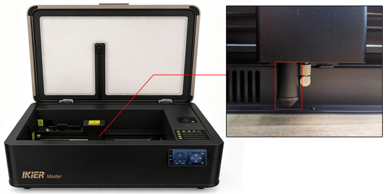
Figure 55
- Use the Z-axis movement controls on the control screen to move the Z-axis upward. When it reaches the top position, check whether the upper limit switch is triggered. If it can be triggered, the upper limit switch is functioning normally.
① If the lower limit switch cannot be triggered properly:
Open the cover at the top of the Z-axis and check whether the lower limit switch cable is loose (see Figure 56).
If the cable connection is normal, the lower limit switch board may be faulty. Please refer to the Master limit switch replacement video for replacement instructions.
② If the upper limit switch cannot be triggered properly:
Open the cover at the top of the Z-axis and check whether the upper limit switch cable is loose (see Figure 57).
Disconnect and reconnect the cable, then manually press the upper limit switch to check whether it can be triggered normally.
If it still cannot be triggered, the upper limit switch board is likely faulty. Please refer to the Master limit switch replacement video for replacement instructions.
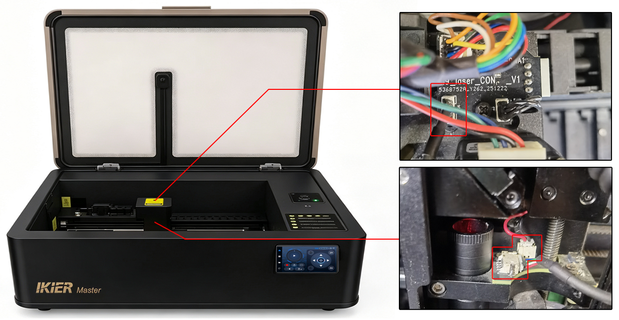
Figure 56
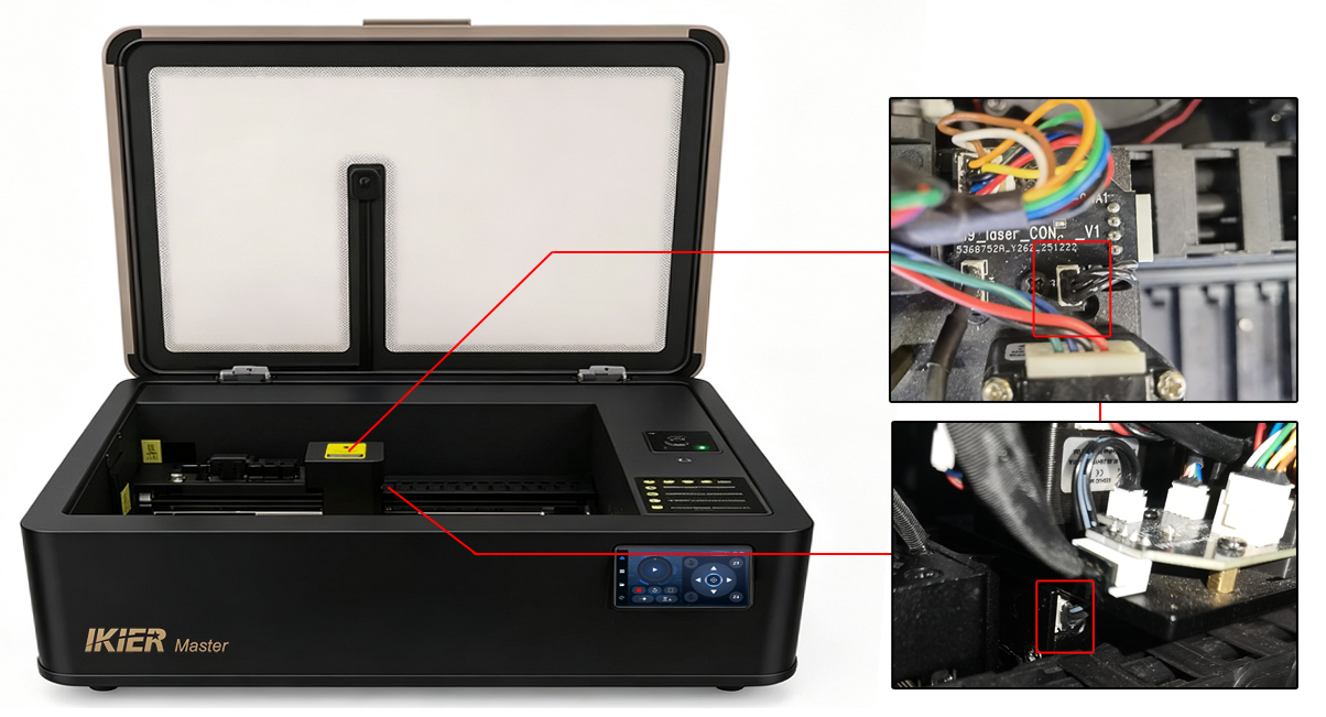
Figure 57
- Check the motor status:
If the Z-axis motor makes noise during the auto focus process but does not move:
-
Use the Z-axis movement controls on the control screen to move the Z-axis up and down and check whether the movement is smooth.
-
If the Z-axis moves smoothly using the control buttons, the issue may be firmware-related. Please send the machine’s Serial Number (see Figure 58), a video showing the issue, and the troubleshooting steps already performed to customer service for assistance.
-
If abnormal behavior also occurs when using the control buttons, open the cover at the top of the Z-axis and check whether the Z-axis motor cable is loose. Disconnect and reconnect the cable. Also check whether the cable is damaged (see Figure 59).
-
If the cable and connector appear normal, manually rotate the Z-axis motor lead screw (see Figure 60) to check whether the Z-axis linear guide rail is functioning properly. If any abnormality is found, please send a video showing the issue to customer service for assistance.
-
Figure 58
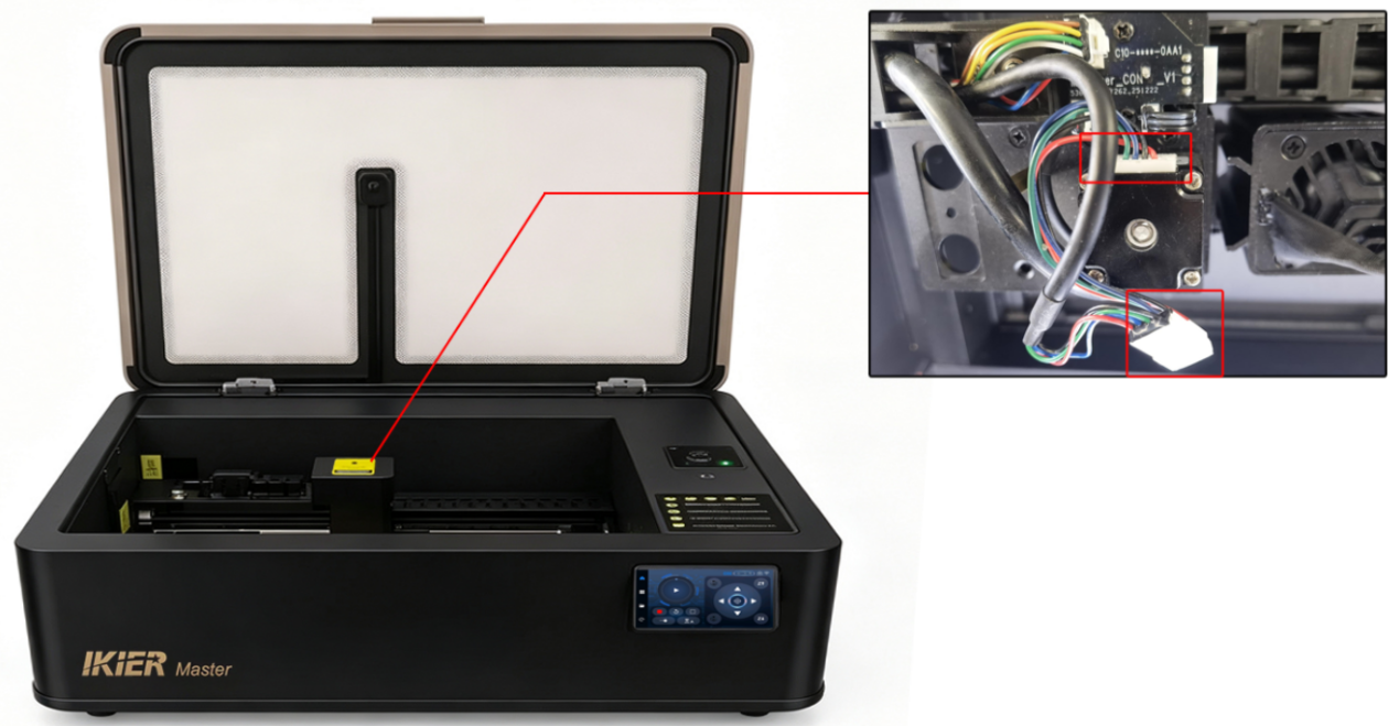
Figure 59
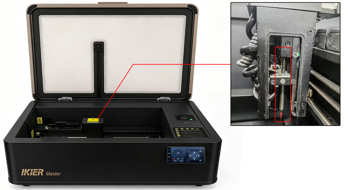
Figure 60
- If the above steps do not resolve the issue, please send the following to customer service:
-
A video showing the auto focus failure
-
A video showing the troubleshooting process
-
The machine’s Serial Number
¶ Master Displays “Travel Limit Reached” During Operation
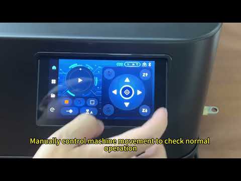
Solution: Please refer to the Master travel limit troubleshooting guide.
- Check whether a limit switch has been triggered:
Observe under what conditions the alarm appears and whether a limit switch has been physically triggered.
If a limit switch has been triggered, check whether the engraving file size exceeds the machine’s working area:
-
CO₂ mode working area: 500 mm × 300 mm
-
IR mode working area: 300 mm × 265 mm
If no limit switch appears to have been triggered, continue with the following troubleshooting steps.
- Check the limit switches:
Use the control screen to move the machine up, down, left, and right, and check whether all X-axis and Y-axis limit switches can be triggered properly.
You can also move the Z-axis to confirm whether all three Z-axis limit switches can be triggered normally.
If any switch cannot be triggered, or if the alarm appears during movement, follow these steps:
-
First, confirm that the limit switch cables are securely connected. Disconnect and reconnect the cables.
-
Check whether the limit switches have any physical damage.
- Check the machine firmware version:
In AtomStack Studio or LightBurn, check whether the machine firmware version is correct (see Figure 61 and Figure 62).
If the firmware version is not the latest version, please update it to the latest release.
Figure 61
Figure 62
- If the above steps do not resolve the issue, please send the following to customer service:
-
A video showing the issue
-
The troubleshooting steps already performed
-
A photo of the machine’s Serial Number (see Figure 63)
Figure 63
¶ The Master Stops During Engraving

Solution: Please refer to the Master engraving interruption troubleshooting guide.
- Check the software alarm messages:
After the machine stops, check whether the software displays any error or alarm messages. If there is an error message, troubleshoot according to the prompt.
- Travel Limit Reached
Please refer to the section: “The Master Displays ‘Travel Limit Reached’ During Operation.”
- Alarm 1
A limit switch has been triggered. Check carefully whether the engraving file exceeds the machine’s working area, or whether the machine has collided with a limit switch during operation.
- Alarm 3
The machine detected an automatic stop signal or another stop condition. Further troubleshooting is required based on the specific trigger condition.
- Alarm 12
A flame alarm has been triggered. Please check the following:
-
Whether the engraving/cutting material is MDF, balsa wood, or similar materials
-
Try replacing the material with basswood for testing
-
Check whether the engraving/cutting design contains overly dense lines; if so, increase the speed and increase the number of engraving/cutting passes
-
Check whether direct sunlight is shining into the machine, as direct sunlight may falsely trigger the flame alarm
-
Alarm 13
The enclosure door is open. Check whether the enclosure door was opened during engraving.
If the door was not opened, the enclosure door limit switch may be faulty. Please send a video showing the issue, the alarm message, and the machine’s Serial Number to customer service for assistance.
If replacement is required, please refer to the Master limit switch replacement video.
- If no alarm message is displayed, continue with the following troubleshooting steps.
- Check the engraving progress bar in the software:
If the engraving progress bar in the software continues running even though the machine has stopped, the issue may be caused by abnormal data transmission.
Try the following:
-
Use a different USB port on the computer
-
Replace the Type-C cable
-
Try a different engraving software (such as AtomStack Studio or LightBurn)
- If the above steps do not resolve the issue, please send the following to customer service:
-
A video showing the issue
-
Screenshots of any software messages or alarms
-
The troubleshooting steps already performed
-
A photo of the machine’s Serial Number (see Figure 64)
Figure 64
¶ The Master Does Not Respond After Pressing the Start Button
- Check the machine status:
-
Home the machine first
-
Make sure the enclosure door is closed
-
Confirm that the water tank has been filled and that the water level is above the minimum level
-
Check the machine temperature displayed in the software
- Check the connection status:
Use the directional controls in the software to move the machine and check whether the connection has been disconnected.
- Check for software prompts:
After pressing the Start button, check whether any message or warning appears in the software. If a prompt appears, troubleshoot according to the message.
- Check the control screen information:
Check whether any alarm or warning message is displayed on the control screen.
- Restart the machine and software:
Close the machine and the software completely, then restart both and try again.
- Try different software:
Try using a different control software, such as AtomStack Studio or LightBurn.
- If the above steps do not resolve the issue, please send the following to customer service:
-
A video showing the issue
-
Screenshots of any software prompts or error messages
-
The troubleshooting steps already performed
-
A photo of the machine’s Serial Number (see Figure 65)
Figure 65
¶ The Machine Moves During Engraving, but the Laser Tube Does Not Emit Laser

Solution: Please refer to the Master laser tube no-output troubleshooting guide.
- Check the laser power supply:
Turn off the machine power, open the internal shield panel, then power the machine back on and check whether the indicator light on the laser power supply (located on the right side near the laser tube) lights up normally.
If the indicator light does not turn on, the laser power supply may be faulty. Please send a video showing the issue and the machine’s Serial Number to customer service for assistance.

If replacement is required, please refer to the Master laser power supply replacement video.
- Check the laser power supply wiring:
With the power disconnected, inspect whether any cables connected to the laser power supply are loose. Disconnect and reconnect the cables, then test again.
- Check the laser tube wiring:
With the power disconnected, carefully inspect whether the wiring connections at both ends of the laser tube are secure.
Also check whether any cables are damaged or broken.
- Check the condition of the laser tube:
With the power disconnected, carefully inspect the laser tube for any signs of damage or cracking.
If damage is found, please provide clear photos, videos, and the machine’s Serial Number to customer service for assistance.
If replacement is required, please refer to the Master laser tube replacement video.
- If the above steps do not resolve the issue, please send the following to customer service:
-
A video showing the issue
-
Screenshots of any software prompts or error messages
-
The troubleshooting steps already performed
-
A photo of the machine’s Serial Number (see Figure 66)
Figure 66
¶ The Distance After Master Auto Focus Is Not 8 mm
- Confirm the material type:
If the material is soft or flexible, please use manual focusing instead. The correct focus distance is 8 mm.
Use the Z-axis movement controls on the control screen to adjust the height manually. It is recommended to use Jog Mode for more precise adjustment.
- Confirm the auto focus process:
The auto focus sequence works as follows:
-
The Z-axis first moves to the highest position
-
Then moves downward until the lower limit switch is triggered
-
Finally moves upward to the standard 8 mm focus height
If the auto focus process appears normal but the final distance is not 8 mm, you can adjust the auto focus distance parameter in LightBurn or LaserGRBL.
The default auto focus parameter value is 1.5.
Correction value calculation:
- If the actual measured distance is greater than 8 mm:
[
1.5 - (\text{actual measured value} - 8)
]
- If the actual measured distance is less than 8 mm:
[
1.5 + (8 - \text{actual measured value})
]
In the LightBurn Console window (see Figure 67), enter:
$autoFocus/depth_max_mm=correction_value
Then press Enter.
Example:
If the actual auto focus distance measures 9 mm, then:
[
1.5 - (9 - 8) = 0.5
]
So the command should be:
$autoFocus/depth_max_mm=0.5

For detailed operation steps, please refer to the Master auto focus distance adjustment guide.
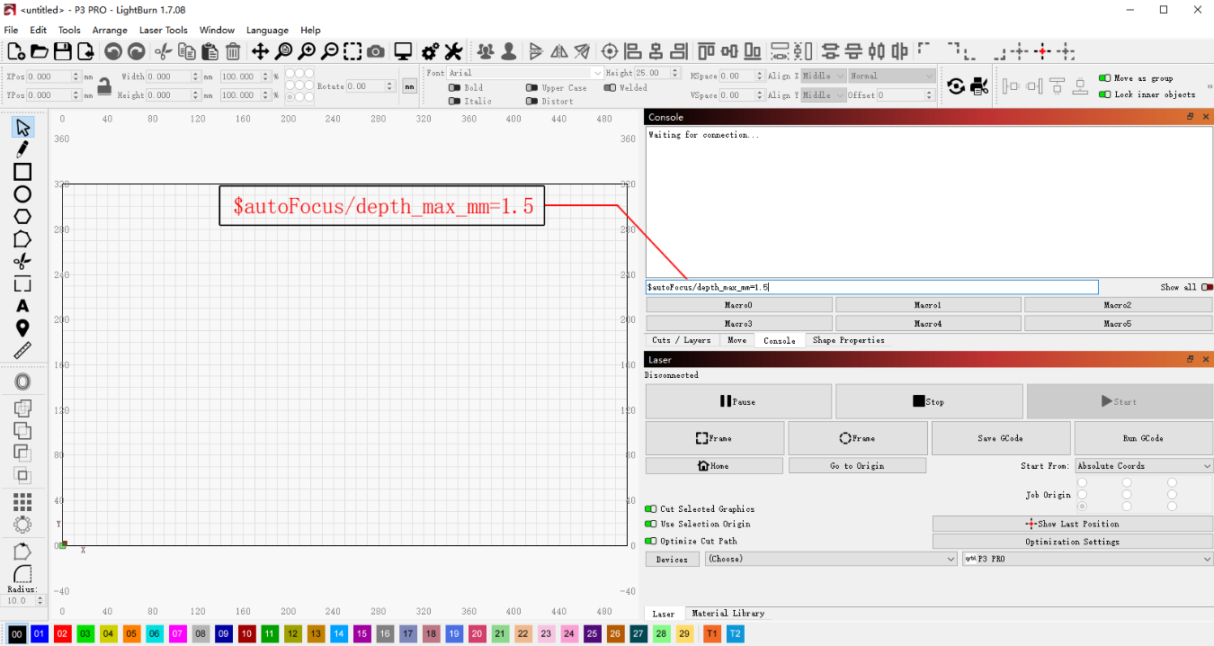
Figure 67
¶ The LED Light Strip Inside Master Enclosure Does Not Turn On

Solution: Please refer to the Master enclosure LED light strip troubleshooting guide.
- Confirm that the machine has started normally:
After powering on, make sure the mainboard starts normally, the buzzer sound is heard, and the machine can connect properly.
- Check the LED light strip wiring:
Turn off the power and remove the outer cover. Check whether the LED light strip cable connections are loose.
If you have a multimeter, you can also measure whether the voltage on the cable is abnormal.
- If the above checks show no issues, the LED light strip may be faulty. Please send the following to customer service:
-
A video showing the issue
-
Screenshots of any software prompts or messages
-
The troubleshooting steps already performed
-
A photo of the machine’s Serial Number (see Figure 68)

For replacement instructions, please refer to the Master enclosure LED light strip replacement video.
Figure 68
¶ Smoke and Dust Inside the Master Enclosure Cannot Be Exhausted in Time and Leak Out Through the Door Gaps

Solution: Please refer to the Master smoke exhaust troubleshooting guide.
- Check whether an air purifier is being used:
If an air purifier is connected, disconnect the exhaust hose from the purifier and vent it directly outdoors. Then check whether the smoke inside the enclosure can be exhausted properly.
If the smoke can be exhausted normally after bypassing the purifier, the issue is likely caused by the air purifier.
- Check the exhaust fan condition:
The internal shield panel must be removed first.
- Check whether the fan is clean:
If there is excessive dust buildup on the fan, please refer to the “Master Enclosure Cleaning” section for cleaning instructions.
- Check whether the fan blades are intact:
If any fan blades are broken or damaged, please send clear photos and a photo of the machine’s Serial Number (see Figure 69) to customer service for assistance.
Figure 69

For fan replacement instructions, please refer to the Master enclosure fan replacement video.
- Check the fan wiring:
After removing the shield panel, inspect the fan cable connections and confirm that the cables are securely connected (see Figure 70).
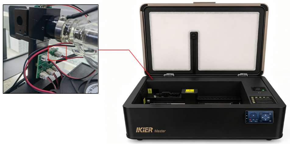
Figure 70
- Supply power directly to the fan:
Use an external 12V or 24V power adapter and connect it to the fan terminals using two additional wires to check whether the fan rotates normally (see Figure 71).
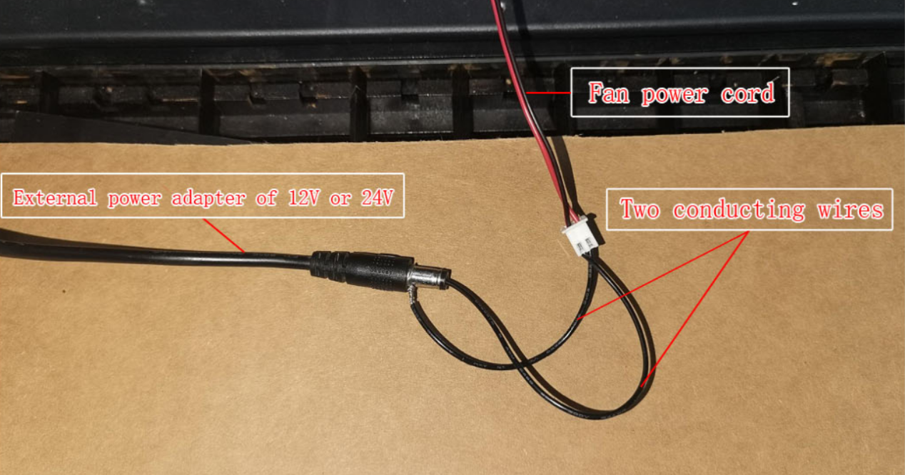
Figure 71
- If the fan is confirmed to be faulty, please send the following to customer service:
-
A video showing the issue
-
The troubleshooting steps already performed
-
A photo of the machine’s Serial Number
¶ The Master’s Flame Detection Function Fails and No Alarm Is Triggered Even When a Fire Occurs

Solution: Please refer to the Master flame detection troubleshooting guide.
- Confirm that the flame detection function is enabled:
After connecting the machine, check in AtomStack Studio whether the flame detection function is enabled (see Figure 72).
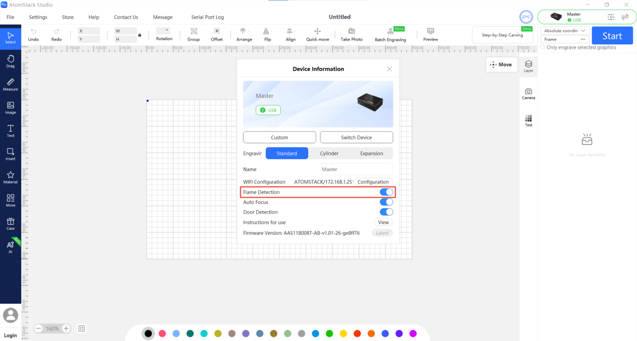
Figure 72
- Check the flame detection board wiring:
Open the Z-axis shield cover and check whether the cable connected to the flame detection board is loose (see Figure 73).
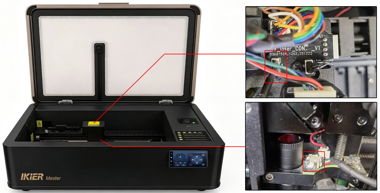
Figure 73
Also inspect the cable for any damage or breakage.
- Test the flame detection board function:
Use a regular lighter (not a windproof lighter) to create a flame and place it under the flame detection board for about 1 second. Check whether the alarm is triggered.
If the alarm is not triggered while all other machine functions operate normally, the flame detection board is likely faulty.
Please send the following to customer service:
-
A video showing the issue
-
The troubleshooting process already performed
-
A photo of the machine’s Serial Number (see Figure 74)
Figure 74

For replacement instructions, please refer to the Master flame detection board replacement video.
¶ The Master’s Flame Detection Function Triggers False Alarms When No Fire Is Present
- Check the working environment:
If the engraving machine is exposed to direct sunlight, the flame alarm may be triggered falsely. Move the machine to another location or block direct sunlight exposure.
- Check the engraving or cutting file design:
If the engraving or cutting file contains extremely dense lines, it may falsely trigger the flame alarm. Try increasing the speed and increasing the number of passes to reduce the chance of false alarms.
- Check the material being processed:
If the engraving or cutting material is highly flammable, such as MDF, balsa wood, cork, or paper, it may easily trigger the flame alarm.
You may disable the flame detection function before engraving or cutting these materials. However, when the flame detection function is disabled, the machine must be continuously supervised during operation to prevent accidents.
- Adjust the flame detection sensitivity:
If the flame alarm is frequently triggered when processing a certain material even though no actual fire occurs, you may adjust the flame detection sensitivity appropriately.
Note
-
If the sensitivity settings are changed, they should be restored to the original values when switching to different materials.
-
The machine must still be supervised during operation after modifying these settings.
Adjustment commands:
$fire_alarm/overflow_value=10
Adjusts the number of trigger events required after exceeding the threshold.
(Usually does not need to be modified.)
$fire_alarm/threshold_value=97
Adjusts the flame detection threshold.
The higher the value, the more difficult it is to trigger the flame alarm.
Only modify the number after the equals sign.
- If the above steps do not resolve the issue, please send the following to customer service:
-
A video showing the issue
-
The troubleshooting steps already performed
-
A photo of the machine’s Serial Number (see Figure 75)
For replacement instructions, please refer to the Master flame detection board replacement video.
¶ Master Displays a Water Temperature Abnormality Alarm

Solution: Please refer to the Master water temperature abnormality troubleshooting guide.
- Check the water tank level:
Make sure the water level in the tank is not too low. If the water level is low, add the required cooling liquid.
- Check the working environment:
The recommended operating environment for the Master is 5°C–35°C.
-
If the temperature is below 5°C, add non-corrosive antifreeze coolant. Please refer to the “Master Water Tank Refill and Replacement Guide” section for details.
-
If the ambient temperature exceeds 35°C, use air conditioning to lower the room temperature.
Note
-
When the water temperature exceeds 35°C, the machine will issue a high-temperature warning.
-
When the water temperature exceeds 40°C, the machine will enter alarm mode and automatically stop operating.
- Check the water temperature reading:
Use AtomStack Studio or the control screen to check whether the displayed water temperature is normal.
If the water temperature exceeds 35°C, stop the machine and allow it to rest for 10 minutes. Also check whether the working environment temperature is too high.
- Check the temperature sensor:
If the ambient temperature is normal, the water level is normal, and the machine still reports a water temperature abnormality shortly after startup, check whether the water tank temperature sensor cable is loose (TEMP connector, see Figure 76).
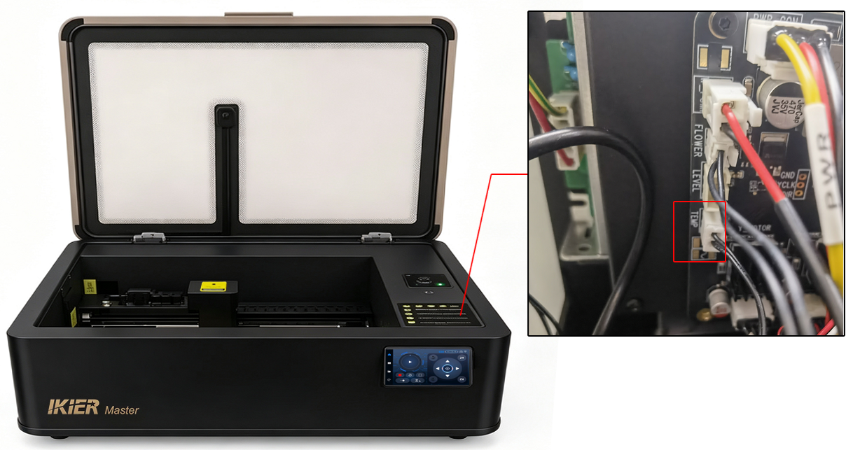
Figure 76
If the cable connection is secure, the temperature sensor may be faulty.
¶ Master’s Door-opening Detection Function Fails and the Machine Does Not Stop When the Enclosure Door Is Opened During Operation

Solution: Please refer to the Master door-opening detection troubleshooting guide.
- Confirm that the door detection function is enabled:
After connecting the machine, check whether the door detection function is enabled in either:
-
the machine settings on the control screen, or
-
the machine function settings in AtomStack Studio (see Figure 77).
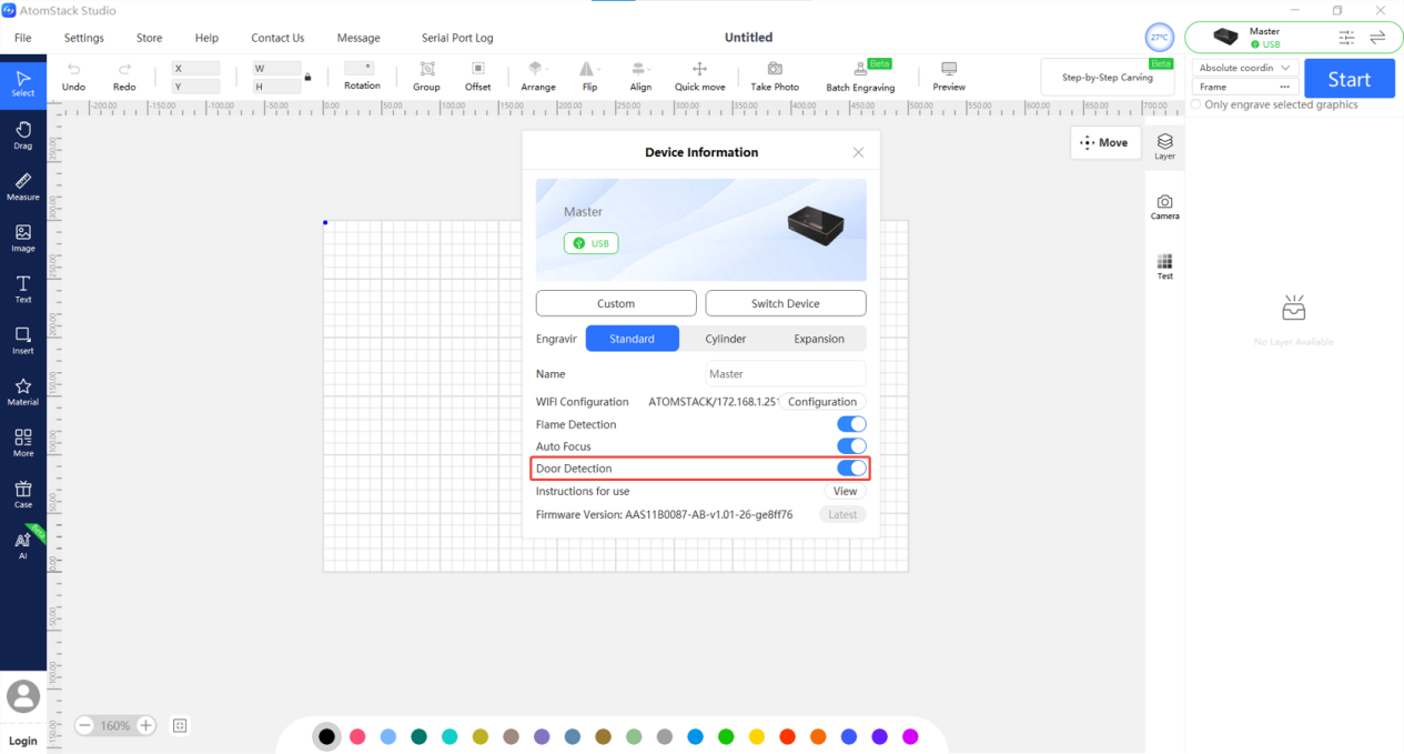
Figure 77
- Check the enclosure door limit switch:
- Hall sensor switch (please distinguish carefully):
Start an engraving task and open the enclosure door. If no alarm is triggered, the Hall sensor switch may be faulty.
Please send the following to customer service:
-
A video showing the issue
-
A photo of the machine’s Serial Number (see Figure 78)
Figure 78
For replacement instructions, please refer to the Master limit switch replacement video.
Note
Before receiving the replacement part, if continued operation is necessary, you may disable the door detection function in the software.
However, for safety reasons, do not open the enclosure door while the machine is operating.
- Enclosure door limit switch (please distinguish carefully):
Start an engraving task. After opening the enclosure door, manually press and release the limit switch lever to check whether the machine stops.
If the machine does not stop, the enclosure door limit switch may be faulty.
Please send the following to customer service:
-
A video showing the issue
-
A photo of the machine’s Serial Number
For replacement instructions, please refer to the Master limit switch replacement video.
¶ After Using the Rotary Attachment with Master, the Engraved Output Appears Mirrored

Solution: Please refer to the troubleshooting guide for mirrored engraving output when using the rotary attachment with Master.
- Check whether mirror mode is enabled:
In the rotary settings of AtomStack Studio or LightBurn, check whether the “Mirror Output” option is enabled (see Figure 79 and Figure 80).
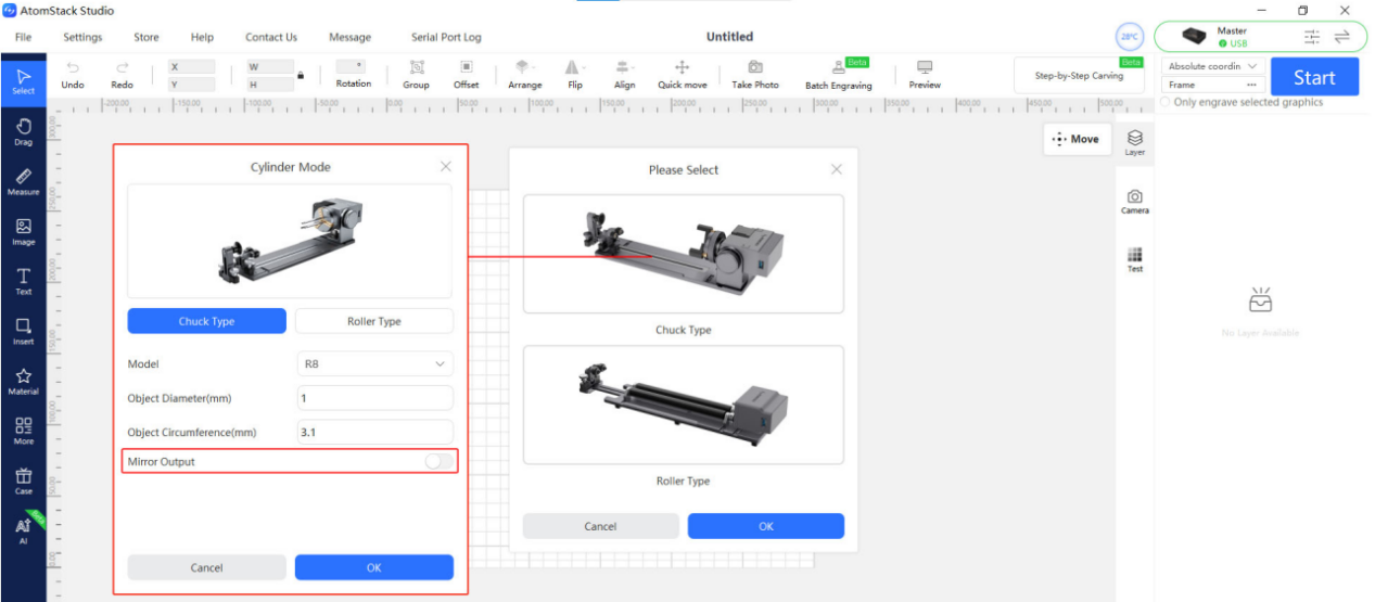
Figure 79
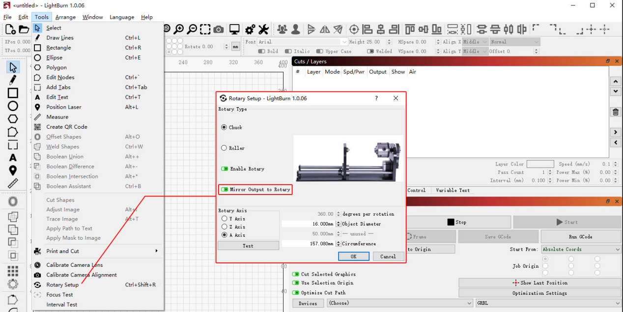
Figure 80
- Check the rotary attachment orientation:
The motor side of the rotary attachment must face the right side.
- Check the A-axis reverse direction setting:
In LightBurn or LaserGRBL:
-
Open the Edit menu
-
Select Machine Settings
-
Find “A Direction Pin Invert ($3)”
If the setting is currently True, change it to False.
If it is currently False, change it to True.
Then click Write, followed by OK to save the settings (see Figure 81).
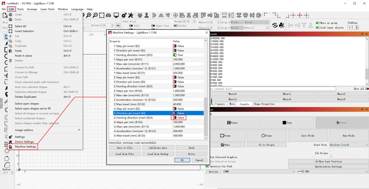
Figure 81
¶ After Using the Rotary Attachment with Master, the Engraved Output Appears Distorted
Solution: Please refer to the troubleshooting guide for distorted engraving output when using the rotary attachment with Master.
- Check the software parameter settings:
Verify that the rotary attachment parameters in the control software are set correctly.
Please refer to the “Master Rotary Attachment Usage” section for the correct settings.
- Check the placement of the rotary attachment:
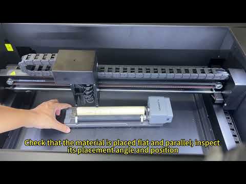
Make sure the rotary attachment is positioned parallel to the X-axis.
- Check the rotary attachment operating condition:
Carefully observe whether the material rotates abnormally while the rotary attachment is operating.
Also check whether there is oil or residue on the material surface that could reduce friction and cause slipping.
Note
If using the R8 chuck rotary attachment, make sure the engraving surface is level after the material is clamped.
¶ Master Cannot Detect the Rotary Attachment
- Check the USB cable connection:
The rotary attachment must be connected using the supplied USB cable (see Figure 82).
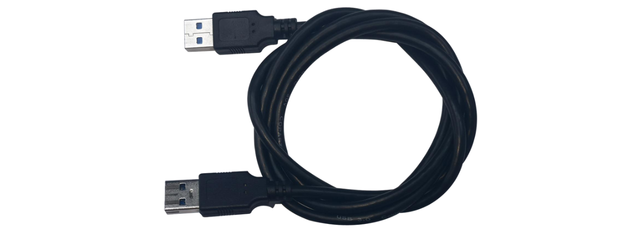
Figure 82
- Check the USB connector on the mainboard:
Open the internal shield panel and check whether the USB connector on the mainboard is loose.
- If the above steps do not resolve the issue, try replacing the rotary auto-detection board and the expansion interface adapter board.
For replacement instructions, please refer to:
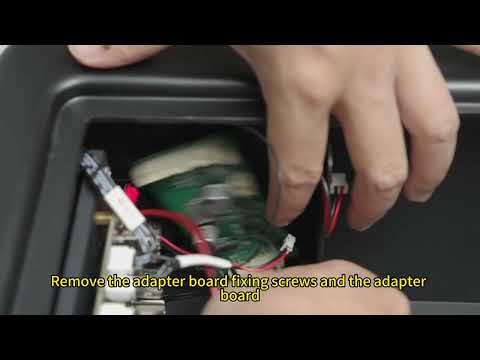
- the Master expansion interface adapter board replacement video
¶ Master Cannot Detect the USB Drive
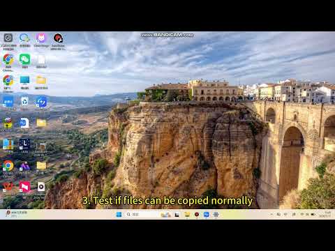
Solution: Please refer to the Master USB drive detection troubleshooting guide.
-
Remove and reinsert the USB drive, then restart the machine to check whether the USB drive can be detected.
-
Insert the USB drive into a computer and check whether it can be read normally.
-
Format the USB drive on a computer using the FAT32 file system.
-
Try using another USB drive with a capacity of 32 GB or less and check whether the machine can detect it automatically.
-
If the above steps do not resolve the issue, please send the following to customer service:
-
A video showing the issue
-
The troubleshooting steps already performed
-
A photo of the machine’s Serial Number (see Figure 83)
Figure 83
¶ Master Cannot Upgrade the Firmware

Solution: Please refer to the Master firmware upgrade troubleshooting guide.
- Confirm the firmware version:
Check the machine’s current firmware version in AtomStack Studio or the mobile app.
If the firmware name does not match the upgrade package, the firmware cannot be upgraded.
- Confirm that a USB drive is inserted:
A USB drive must be inserted into the machine during the firmware upgrade process, as it is used as the storage device.
- Confirm the firmware file format:
The firmware file must be in .bin format and must be placed in the root directory of the USB drive.
If you are upgrading by copying the firmware file to the USB drive manually, please make sure the file is not placed inside any folder.
- Confirm that the USB drive is functioning properly:
Insert the USB drive into a computer and check whether it can be read normally.
You can also export an NC or GC file from the software, copy it to the USB drive, insert the USB drive into the machine, and check on the control screen whether the file can be read correctly.
¶ Master Still Displays “Tray Not Inserted” After the Tray Has Been Installed
- Check whether the drawer Hall sensor switch is functioning properly:
Place a magnet near the Hall sensor switch located at the front-left bottom area of the machine (see Figure 84) and check whether the alarm is cleared.
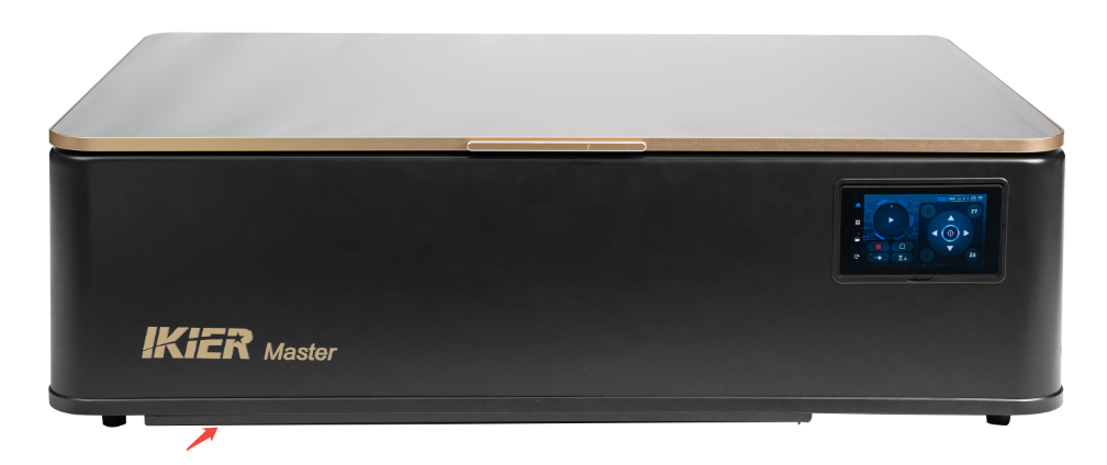
Figure 84
- Check the drawer Hall sensor wiring:
Open the machine enclosure and check whether the Hall sensor cable is connected properly.
If the cable connection is secure, the Hall sensor switch may be faulty.
Please send the following to customer service:
-
A video showing the issue
-
The troubleshooting steps already performed
-
A photo of the machine’s Serial Number (see Figure 85)
For replacement instructions, please refer to the Master limit switch replacement video.
Figure 85
¶ Master Timing Belt Is Broken
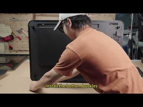
Solution: Please refer to the Master timing belt replacement video.
Note
Replacing the Y-axis timing belt requires removing the outer cover.
When replacing the X-axis timing belt, loosen the timing belt tensioner first.
¶ After Installing the 1.6W IR Laser Module on Master, the Software Cannot Detect It

Refer to the troubleshooting video: Master control software does not recognize the infrared laser.
- Confirm that the IR laser module is installed correctly:
There is a dedicated limit switch on the Z-axis designed for the IR laser module. The corresponding function will only be triggered when the IR laser module is installed correctly.
- Check the flame detection board wiring:
Disconnect and reconnect the flame detection board cable, then manually press the limit switch to check whether it can be detected by the software (see Figure 86).
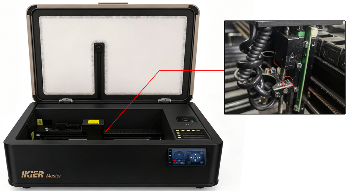
Figure 86
- Check the adapter board wiring:
Open the cover at the top of the Z-axis and check whether any cables on the adapter board are loose.
Disconnect and reconnect the cables, then test again (see Figure 87).
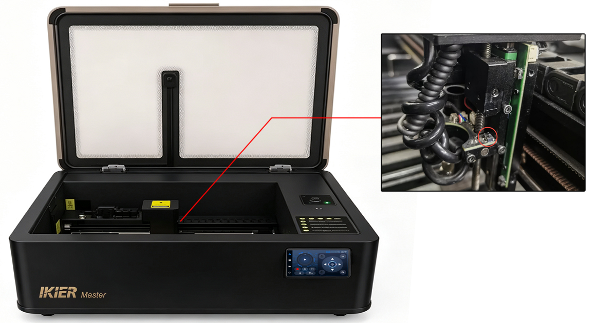
Figure 87
- If the above steps do not resolve the issue, please send the following to customer service:
-
A video showing the issue
-
The troubleshooting steps already performed
-
A photo of the machine’s Serial Number (see Figure 88)
Figure 88
For replacement instructions, please refer to:
-
the Master adapter board replacement guide
-
the Master flame detection board replacement guide
¶ Potential alarm codes for the Master control system
¶ Reference Tables
| Symptom | Check First |
|---|---|
| Cannot power on | Check power cable, emergency stop switch status, switching power supply indicator light, measure motherboard power cable voltage |
| Control screen not displaying | Check control screen for physical damage, check motherboard cable connections, confirm firmware version |
| Connection failed | Check baud rate, Type-C cable port, computer USB port, CH340 driver |
| Camera malfunction | Check computer camera permissions, camera cable connection, verify camera output |
| Power degradation | Check focal distance, software parameters, light path verification, clean reflector and focusing lens |
| Blurry engraving | Check focal distance, clean reflector and focusing lens, ensure material is not shifting |
| Homing failed | Check motor status, limit switch status, firmware version |
| Distorted engraving pattern | Check timing belt tension, X/Y axis synchronous wheel screws, X-axis parallelism |
| Unclosed engraving lines | Check focal distance, engraving parameters, focusing lens, light path; enable constant power, adjust minimum power value |
| Engraving stops midway | Confirm alarm message, check Type-C cable, computer port, try different software |
| Alarm: travel limit reached | Confirm if limit switch was triggered, check limit switch status, firmware version |
| Auto-focus failed | Check material properties, upper/lower limit switch status, Z-axis motor status |
| Flame alarm | Check working environment, line density, engraving material, adjust sensitivity |
| APP connection failed | Confirm WiFi mode is enabled, WiFi name is searchable, turn off mobile data, try a different phone |
| Code | Description | Solution |
|---|---|---|
| ALARM:1 | HardLimit | Observe whether the X-axis, Y-axis, or Z-axis limit switches are being triggered due to physical contact. |
| ALARM:3 | AbortCycle | This code is triggered when the engraving process is manually stopped and does not require clearing. |
| ALARM:5 | ProbeFailContact | Check whether the Z-axis limit switch has been triggered. |
| ALARM:8 | HomingFailPulloff | Homing failed due to limit switch reset failure. Check whether the machine stopped because a limit switch was triggered and whether the motion system is continuously triggering the limit switch. |
| ALARM:9 | HomingFailApproach | Please refer to the “Master Homing Failure” section. |
| ALARM:11 | MachineTiltAlarm | Tilt alarm detected. Place the machine back on a level surface and restart it. If the issue cannot be cleared, please send a video showing the problem and a photo of the machine’s Serial Number to customer service. |
| ALARM:12 | FlameDetected | Flame detection has been triggered. Restart the machine. If the alarm continues to trigger, please refer to the section “The Master Flame Detection Function Triggers False Alarms When No Fire Is Present” for troubleshooting. |
| ALARM:13 | DoorOpen | Enclosure open alarm detected. Please close the enclosure door. If the alarm still appears, check whether the limit switch is damaged. |