¶ Master Machine Operation
Panel, safety, unboxing, connectivity, focusing, camera, rotary, conveyor, and dual-laser operation.
¶ Master Control Panel Overview
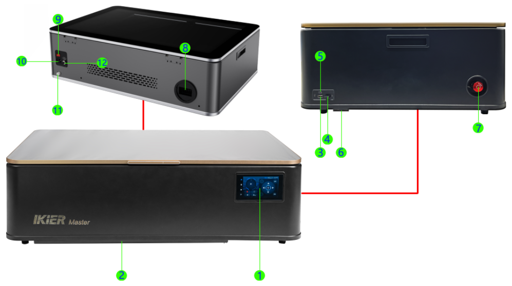
-
Control Panel: Enables offline operation, directional movement, auto focus, switching between IR/CO₂ laser sources, function settings, movement mode settings, ignition, Bluetooth monitoring, and more.
-
Tray: Convenient for cleaning debris and protecting the work surface.
-
USB Drive Port: Slot for inserting a USB flash drive.
-
USB Key Port: The machine operates only when the USB key is inserted (pre-installed at the factory). Without the USB key, the machine cannot emit laser.
-
Computer Port: Used to connect to a computer via a Type-C cable.
-
Expansion Port: Used to connect rotary devices or conveyor feeders. Features automatic recognition and supports connection to R6, R8, and R7.
-
Emergency Stop Switch: In an emergency, press this switch to cut off power and stop operation, ensuring personal and equipment safety. After pressing, rotate clockwise to release and restore power supply.
-
Exhaust Fan: Removes smoke and dust from the enclosure. Can be connected to an external exhaust hose (e.g., connected to an AtomStack D4 purifier or vented outdoors).
-
Power Switch: Turns the machine on or off.
-
Power Socket: AC power input. Ensure the machine is compatible with the local voltage before connecting (Master supports two voltage options: 220V and 110V).
-
Drain Outlet: Unscrew the cap to drain the coolant from the water tank.
-
Air Pump Interface: Allows connection of external air assist. When cutting thicker materials, it is recommended to use external air assist to increase airflow (note: airflow cannot be controlled via the control panel or software when using external air assist).
¶ Safety Instructions for Using Master
Before turning on the machine, please check whether the standard voltage of the engraving machine matches the local mains voltage. Do not connect a machine rated for 110V to a 220V power supply.
It is strictly prohibited to open the Enclosure door and look directly at the laser while the machine is operating.
The machine must be attended at all times during the engraving process.
Processing PVC or chlorine-containing materials is prohibited.
Please ensure that the exhaust system is functioning properly.
¶ Software and File Formats Supported by Master
Software: AtomStack Studio, LightBurn, and the AtomStack App.
File formats: SVG, DXF, PNG, JPG, JPEG, WEBP, GIF, etc. In offline working mode, only GC and NC formats are supported.
¶ Master Unboxing Inspection

Please refer to the Master unboxing video.
Note: Before powering on the machine, carefully check the following items:
After unpacking the carton, inspect the exterior of the machine. If there is any damage, please take clear photos and send them to customer service for assistance.
Before connecting the power, make sure the machine’s power supply matches the local mains voltage. Master is available in two voltage versions: 220V and 110V. Connecting a 110V model to a 220V power supply may damage the internal power supply of the machine.
Before powering on the machine, remove the fixing screws that secure the X-axis and Z-axis.
The machine must be placed and operated on a level surface. Tilting, flipping, or inverting the machine is strictly prohibited.
Make sure the USB key is inserted.
Before powering on the machine, fill the water tank with suitable distilled water, purified water, or high-purity water. The water level should be between the minimum and maximum level marks, as shown in Figure 1.
Note: Powering on the machine without adding water to the tank may cause the CO₂ tube to crack.
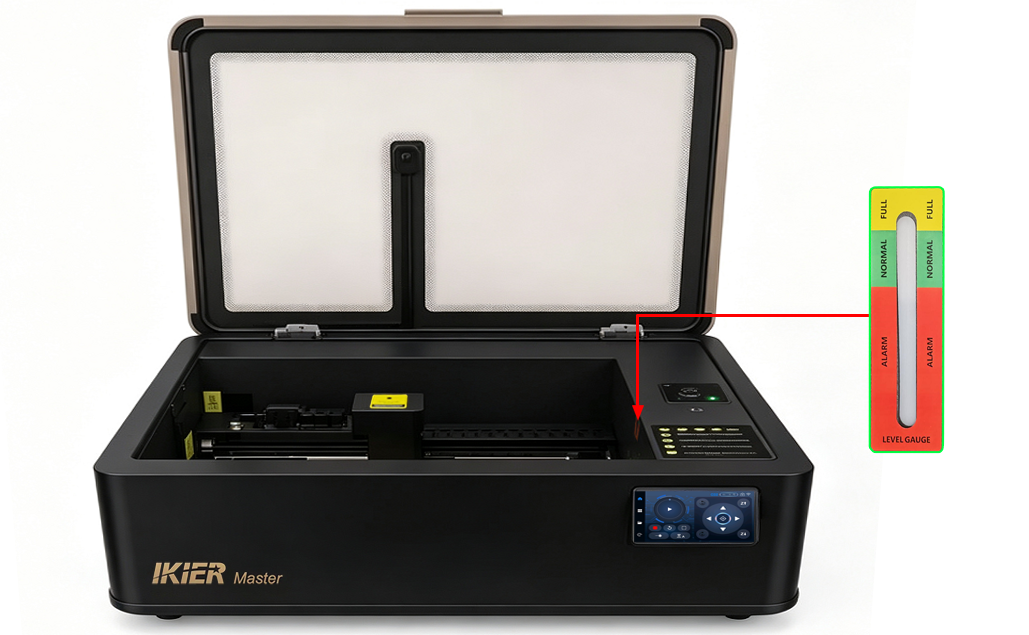
Figure 1
When the ambient temperature is below 5°C, a non-corrosive antifreeze solution must be added to the water tank. The recommended mixing ratio is as follows:
Do not open the Enclosure door while the machine is operating, and never look directly at the laser without proper protection.
The machine must be supervised at all times during operation.
¶ Master Online Connection Setup

Please refer to the Master online operation video.
Note
- When using the machine with a computer for the first time, please install the CH340 serial port driver. Download links are as follows:
-
Windows driver download link: https://asa.atomstack.com/downloadWindowsDrivers.do3
-
macOS driver download link: https://asa.atomstack.com/downloadMacDrivers.do3
- When using AtomStack Studio, the machine can be connected and used directly without additional settings.
When using LightBurn, make sure the baud rate is set to 460800 (see Figure 2), and change the Job Origin to the upper-left corner. It is recommended to import the machine configuration file (included on the USB drive provided with the machine). For the import method, please refer to the video or the “06 Tips for Use” section in the manual, under “9. How to Use LightBurn for Engraving and Cutting.”
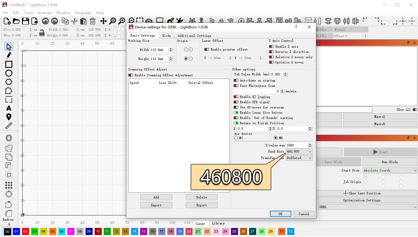
Figure 2
- When using AtomStack Studio, no confirmation setup is required.
When using LightBurn, make sure to add a GRBL controller (see Figure 3) or import the factory configuration file for the Master.
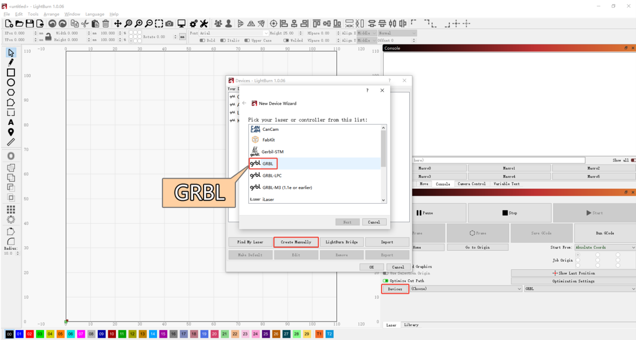
Figure 3
- For Windows computers, the machine can be connected directly using a Type-C to USB-A or USB-C cable.
For macOS or HarmonyOS computers, a docking station/hub (see Figure 4) is required to connect the USB-A end of the Type-C cable.
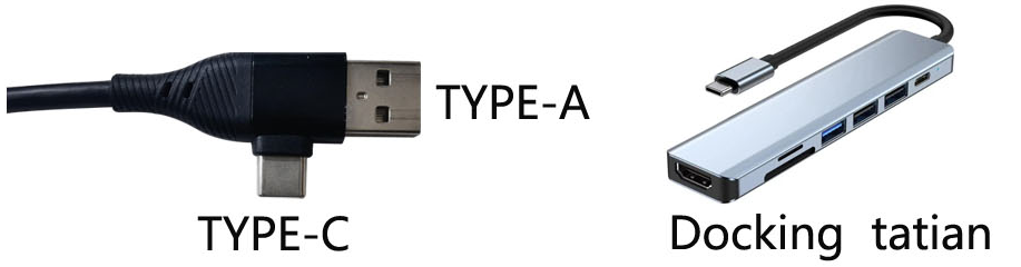
Figure 4
¶ Introduction to the Master Control Screen Functions
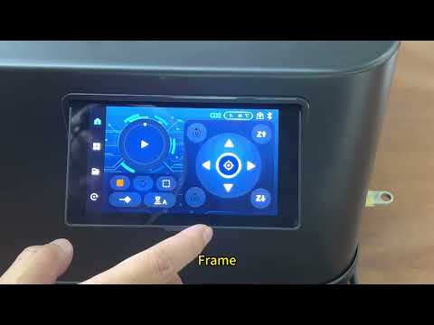
Please refer to the Master control screen function introduction video.
Note
Main Interface: Start/Pause button, Stop button, Frame button, Laser Test button, Auto Focus button, Laser Source Switch button, Temperature Display, X/Y/Z Axis Movement buttons, Reset button, Processing Mode, Network Status, A-axis Movement button, Repeat Engraving, etc. (see Figure 5).
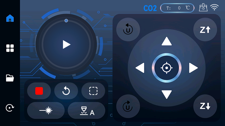
Figure 5
- Start/Pause button: Start or pause offline processing tasks stored on the USB drive.
Note: Only .nc or .gc files are supported.
-
Stop button: Immediately terminate the current processing task.
-
Frame button: Move along the boundary of the processing pattern to display the engraving/cutting area.
-
Laser Test button: Briefly emit the laser for positioning or testing purposes.
-
Auto Focus button: Start the auto-focus function.
-
Laser Source Switch button: Switch between CO₂ mode and IR mode.
-
Temperature Display: Displays the current operating temperature of the machine.
-
X/Y/Z Axis Movement buttons: Control movement along the X, Y, and Z axes.
-
Reset button: Perform homing/reset operation.
-
Processing Mode: Displays the current operating mode of the machine.
-
Network Status: Displays the current network connection status of the machine.
-
A-axis Movement button: Controls the movement of expansion accessories such as rotary attachments or conveyor systems.
-
Repeat Engraving: Repeat the most recent processing task.
Function Interface: Jog Mode, Single-shot Mode, Bluetooth Information, Wi-Fi, Machine Configuration, Language, System Information, System Reset, Laser Source Switching, and Focus Settings (see Figure 6).
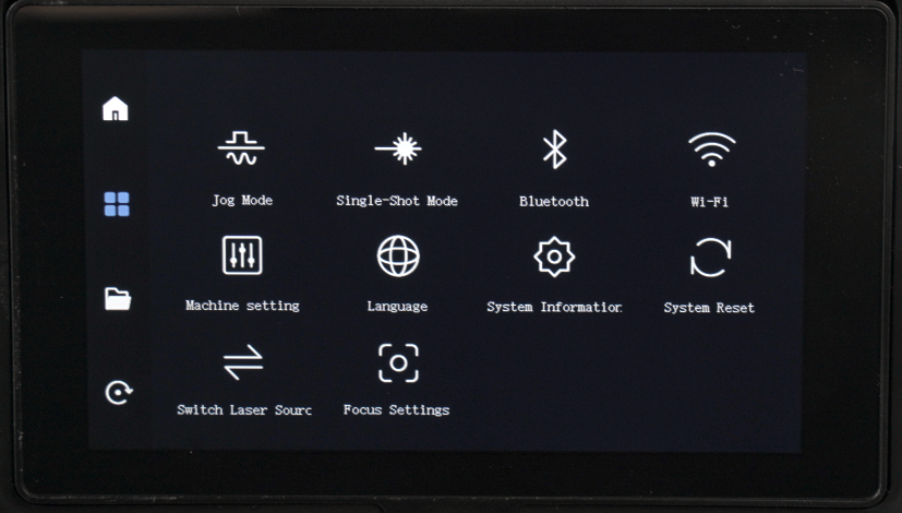
Figure 6
-
Jog Mode: Allows you to set the control method for the movement buttons. When “Jog” mode is selected, the machine moves one step each time the movement button is pressed. When “Continuous” mode is selected, the machine will continue moving while the button is held down. This interface also allows you to set the movement distance and speed for each operation.
-
Single-shot Mode: Allows you to set the pulse duration and pulse power.
-
Bluetooth: Displays the machine’s Bluetooth information and allows switching directly to Bluetooth mode.
-
Wi-Fi: Allows you to connect to Wi-Fi and view the machine’s IP address.
-
Machine Configuration: Allows you to configure machine functions, such as enabling or disabling the air pump, flame detector, interlock switch, and adjusting the lighting brightness.
-
Language: Allows you to select the machine language.
-
System Information: Displays the machine’s hardware information.
-
System Reset: Restores the machine to factory settings.
-
Laser Source Switching: Allows switching between IR mode and CO₂ mode.
-
Focus Settings: Allows you to choose between auto focus and manual focus, and set the movement distance for each adjustment in manual focus mode.
Files: Allows you to view and delete saved files.
Restart: Click to restart the machine.
¶ Focus Adjustment of Master
Please refer to the focus adjustment video of Master.
Note
When using auto focus, the distance between the bottom of the Z-axis assembly and the top surface of the material should be 8 mm.
When using a rotary attachment, manual focus is recommended.
When manual focus is selected, use the directional control buttons on the control screen to adjust the height to 8 mm.
If the material is very thin or soft, manual focus is recommended.
If manual focusing is required frequently, it is recommended to use an 8 mm thick board as a height adjustment gauge.
If an IR laser module is installed, please pay attention to the installation height of the laser head when using the IR laser:
-
First install and secure the laser module, place the material (such as a wooden board), and perform an auto focus operation.
-
After focusing is completed, swing down the fixed-focus rod of the IR laser module (see Figure 7). Loosen the screws securing the IR laser module and allow the fixed-focus rod to touch the top surface of the material.
-
Swing the fixed-focus rod back up, then tighten the screws securing the IR laser module. The focus adjustment is now complete.
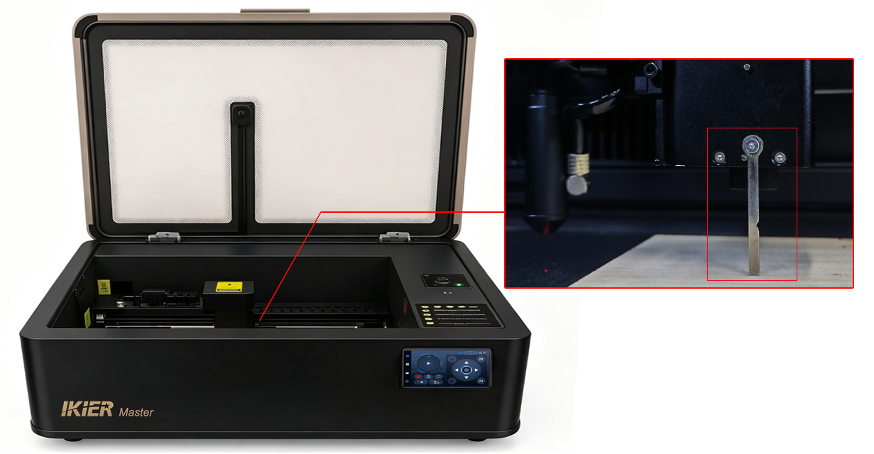
Figure 7
¶ Using the Camera on Master

Please refer to the Master camera operation video.
Note
-
When using the camera, the Enclosure door must be closed. Ensure that the interior of the machine is well lit, and do not use Wi-Fi connection mode while operating the camera.
-
When using the camera, absolute coordinates must be enabled, and the machine must be homed first. Conveyor and rotary attachments cannot be used with the camera function.
-
When using the camera with AtomStack Studio, only alignment is required, as the camera has already been calibrated at the factory.
-
When using the camera, if the thickness of the engraved objects varies significantly, the camera must be recalibrated after changing the object.
-
During camera calibration, make sure a flat sheet of kraft paper is placed and secured on top of the material surface.
-
When calibrating the camera using LightBurn, please note the following:
-
Be sure to distinguish between CO₂ mode and IR mode. If an IR laser module is installed, remove both the IR laser module and its mounting bracket before calibrating the CO₂ laser. When using the IR laser module, the camera must be recalibrated. First, switch to the “AtomStack_Master-1064nm_V1.01” device profile in LightBurn (the IR laser module uses a different coordinate system and a working area of 300 mm × 265 mm).
-
Follow the on-screen instructions for calibration and alignment. When selecting the center points of the four markers, you can zoom in on the image before selecting the points to improve accuracy (see Figure 8).
-
During alignment, right-click in the camera view interface and select “Calibrate Camera Alignment”.
-
LightBurn version 1.7.03 or later is recommended for easier operation and higher calibration accuracy.
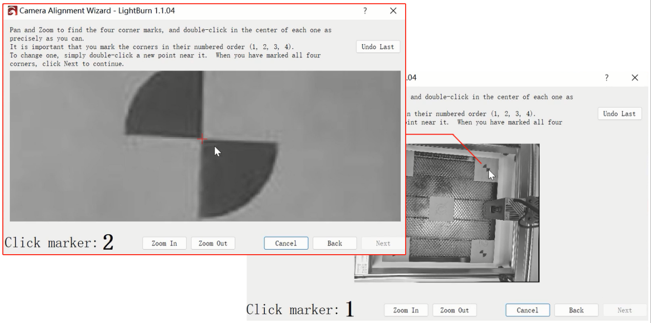
Figure 8
- When performing camera calibration, please disable the Air Assist function on the control screen.
¶ Using the Master Conveyor feeder
Please refer to the Master conveyor operation video.
Note
-
When using the conveyor feeder, it must be used together with the dedicated riser, model Z1.
-
When assembling the conveyor feeder, the panel fixing screws must first be removed. For details, please refer to the R7 user manual.
-
The R7 conveyor feeder supports automatic detection. Simply connect the USB cable supplied with the R7 (see Figure 9) to the machine’s expansion function port to use it.
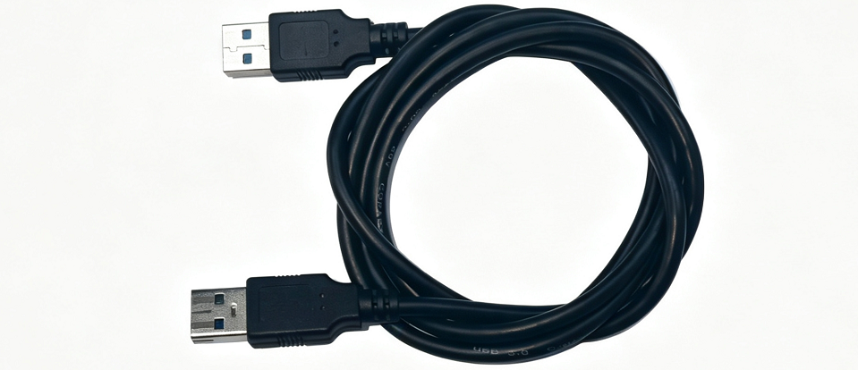
Figure 9
-
Absolute coordinates cannot be used when the conveyor system is connected, so the camera function cannot be used simultaneously.
-
After connecting the conveyor feeder, the working area changes to 500 mm × 800 mm in CO₂ mode and 300 mm × 800 mm in IR mode.
-
When connecting to LightBurn, select “Roller” type in the rotary setup settings, set the rotary axis to the A-axis, and set the diameter to 13 mm (fixed value), as shown in Figure 10.
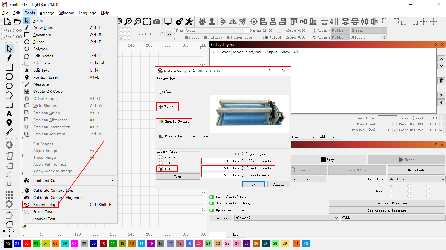
Figure 10
-
When positioning the conveyor feeder, make sure the USB port is facing the front of the machine.
-
When using the R7 conveyor feeder, leave at least 510 mm of clearance between the machine and the wall to prevent the R7 from hitting the wall.
¶ Using the Rotary Attachments on Master

Please refer to the Master rotary attachment operation video.
Note
- Compatible rotary attachment models are R6 and R8. To use them, connect the USB cable supplied with the rotary attachment (see Figure 11) to the machine’s expansion function port.
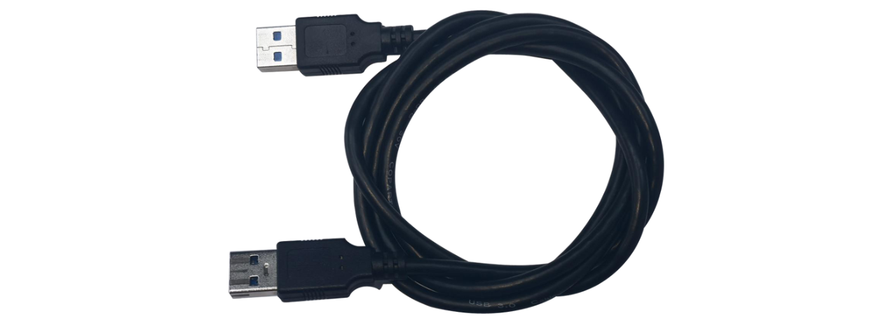
Figure 11
- When using AtomStack Studio:
-
The roller rotary attachment (R6) does not require parameter configuration.
-
The chuck rotary attachment (R8) requires the circumference or diameter of the workpiece to be entered (see Figure 12).
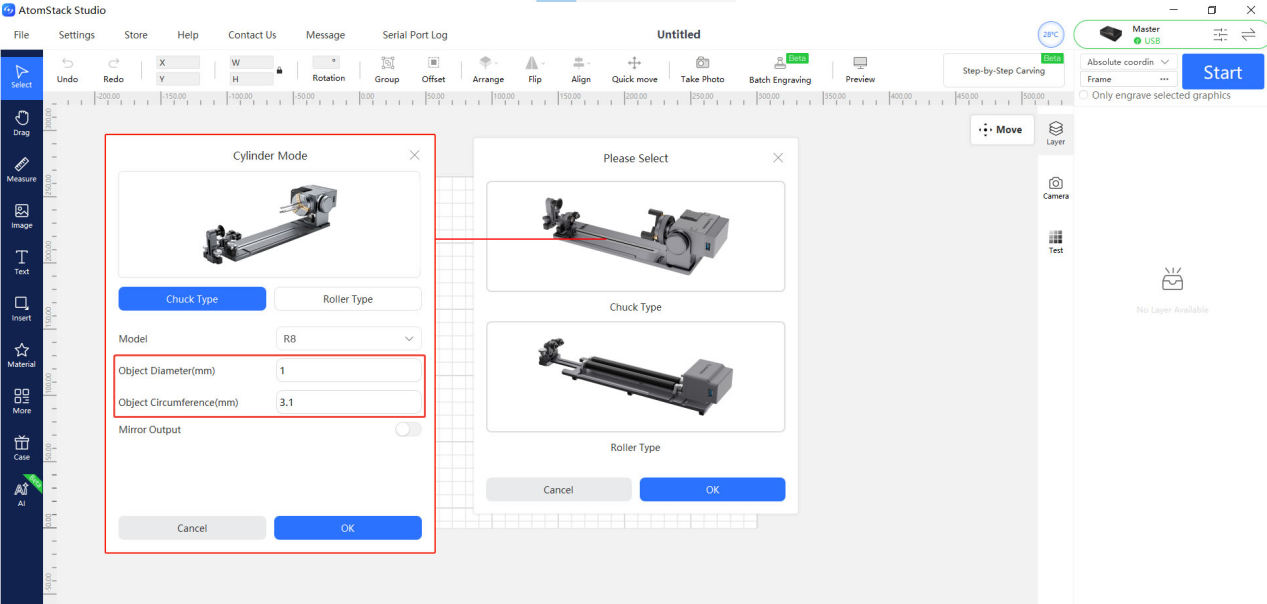
Figure 12
-
Absolute coordinates cannot be used when using a rotary attachment, so the camera function cannot be used simultaneously.
-
Since the Master machine is relatively heavy, using the Z1 riser is recommended when using rotary attachments.
-
When using a rotary attachment, it must be positioned parallel to the X-axis.
-
When using a rotary attachment, the motor side of the rotary attachment must face to the right.
-
When using the R8 chuck rotary attachment, please note the following:
-
The maximum supported diameter for cylindrical objects is 0 mm–80 mm.
-
The maximum supported diameter for spherical objects is 25 mm–80 mm.
-
The maximum supported diameter for ring-shaped objects is 10 mm–70 mm.
-
The maximum supported workpiece weight is 1.5 kg.
- When using LightBurn, rotary parameters must be configured:
-
Select the rotary type (choose “Roller” for R6 and “Chuck” for R8).
-
Set the rotary axis to the A-axis.
For parameter settings:
-
For the R8, enter either the diameter or the circumference of the material (see Figure 13).
-
For the R6, set the roller diameter to 16 mm (fixed value), and enter either the diameter or the circumference of the material (see Figure 14).
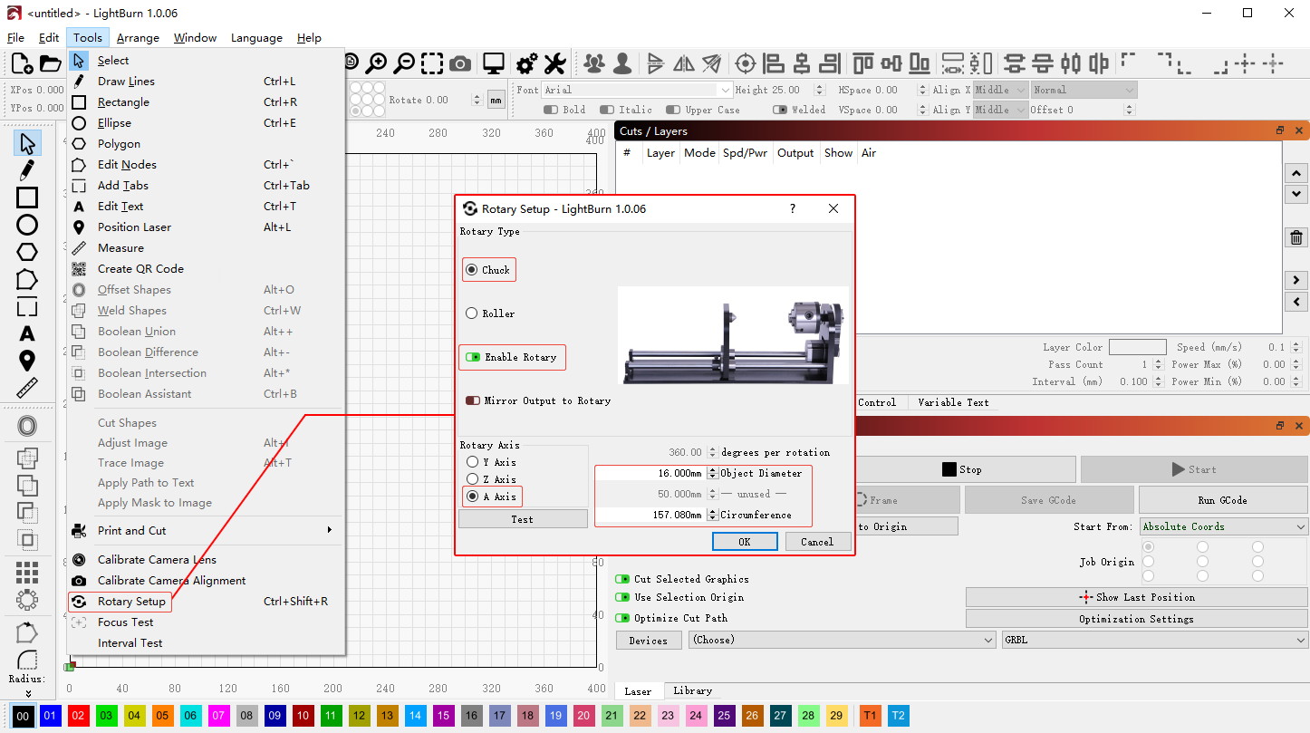
Figure 13
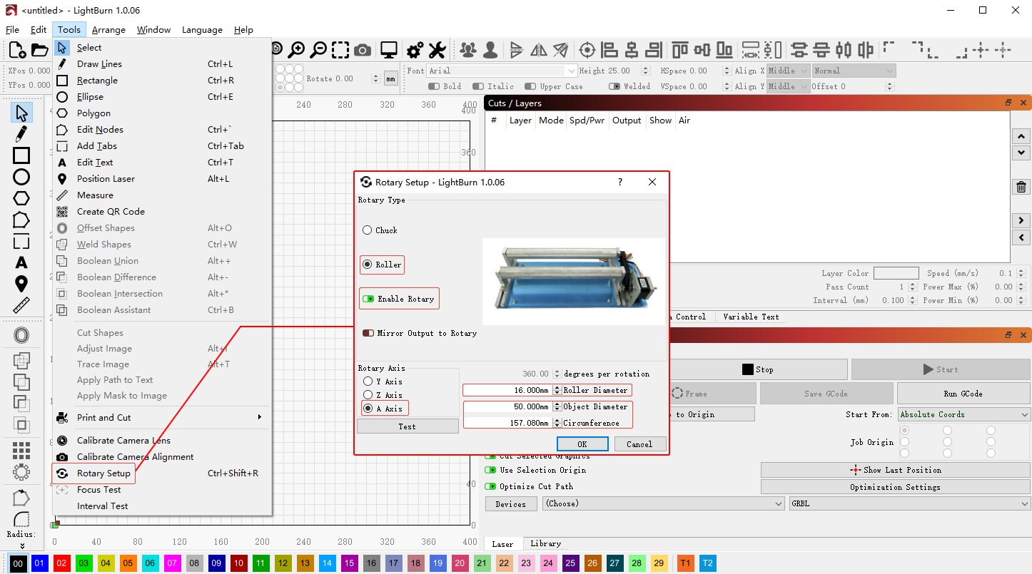
Figure 14
¶ Coordinate Modes in Software for Controlling the Master
-
Current Position: Uses the current position of the laser head as the engraving starting point. The laser can be moved to the desired engraving position using the direction keys on the control panel.
-
User Origin: Allows the user to define the starting position for laser processing.
-
Absolute Coordinates: Uses the home position (0,0) as the reference point, and starts processing based on the coordinates where the workpiece is located.
¶ Optical Path Verification and Calibration of Master

Please refer to the video of Master optical path verification and calibration.
Note
- When verifying the optical path, pay attention to the following two points:
-
Beam Spot Verification: Attach a small piece of white paper to the third mirror (Z-axis mirror) to observe the laser spot position. Use the control screen to move the laser module along the four inner edges of the enclosure and observe whether the laser spot position changes. If the position remains nearly unchanged, the optical path is properly aligned. If there is a noticeable shift, the optical path is misaligned and requires adjustment.
-
Beam Alignment Verification: Attach a piece of masking tape or white paper to the focusing lens frame. Press the laser test button on the control screen or in the software and check whether the red guide beam overlaps with the laser beam spot. If they do not overlap, adjust the screws of the beam combiner module located at the front end of the CO₂ laser tube until the two spots align (see Figure 15).
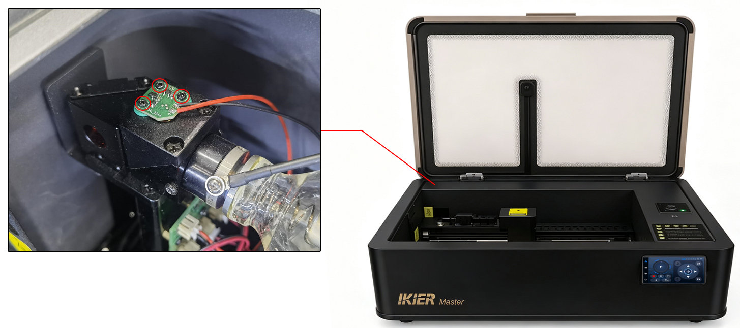
Figure 15
- Cutting Verification: Cut a large square within the working area. After performing a single cutting pass, check whether all four sides of the square are fully cut through. If the material is completely cut through in one pass and all four sides are evenly cut, the optical path is properly aligned. If some sides are cut through while others are not, the optical path is misaligned and requires adjustment.
- When calibrating the optical path, begin by adjusting the first mirror, then adjust the second mirror, and finally the third mirror (see Figure 16).
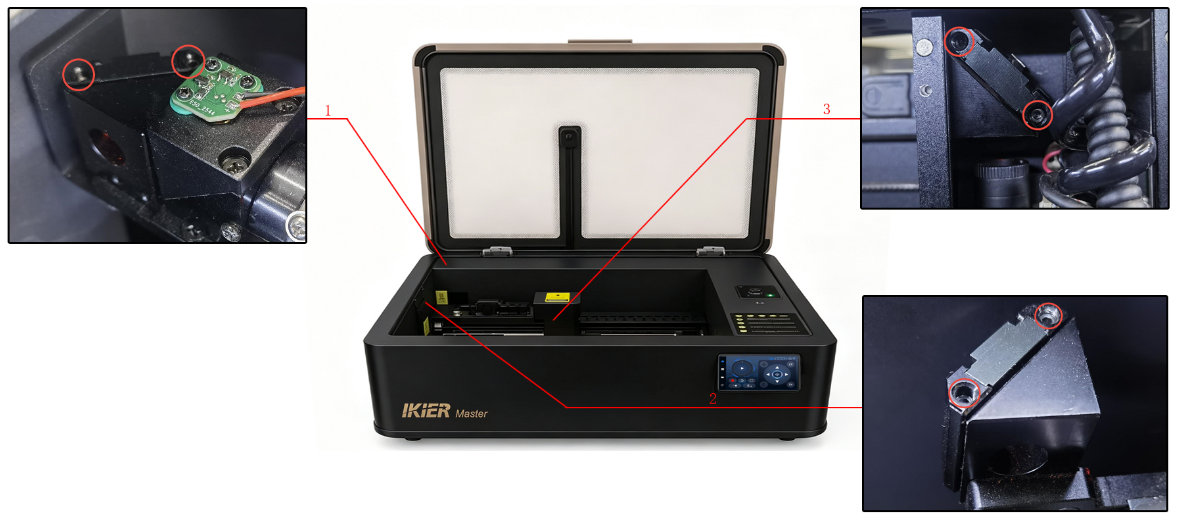
Figure 16
-
When adjusting the optical path, observe all safety precautions and do not operate the machine carelessly.
-
Before testing after adjustment, remove all adjustment tools to prevent them from being damaged by the laser.
¶ Master IR Laser Module Installation Guide

Please refer to the Master IR laser module installation tutorial video.
Note: The IR laser module (infrared laser module) is sold separately.
Note
- First install the IR laser module bracket. When installing the bracket, make sure it presses against the auto-detection sensor on the Z-axis frame (see Figure 17).
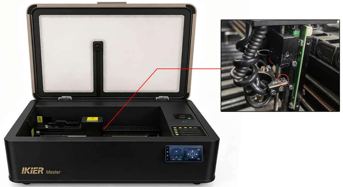
Figure 17
- After installing the IR laser module, the focus distance must be adjusted:
-
First install and secure the laser module, place a rigid material such as a wooden board, and perform an auto focus operation.
-
After focusing is completed, swing down the fixed-focus rod of the IR laser module (see Figure 18). Loosen the screws securing the IR laser module and allow the fixed-focus rod to touch the material surface.
Figure 18
- Swing the fixed-focus rod back up, then tighten the screws securing the IR laser module. The focus adjustment is now complete.
-
After switching to IR mode, the working area will change to 300 mm × 265 mm accordingly.
-
The IR laser module can engrave most common metals. However, please note that it cannot engrave materials such as gold or wood effectively, or the engraving results may be very poor.
¶ Master Dual-Laser Operation Guide

Please refer to the Master dual-laser operation tutorial video.
Note
- The engraving areas for CO₂ mode and IR mode are different:
-
CO₂ mode engraving area: 500 mm × 300 mm
-
IR mode engraving area: 300 mm × 265 mm
- When using AtomStack Studio, different layers within the same project file can be assigned separately to CO₂ mode or IR mode (see Figure 19).
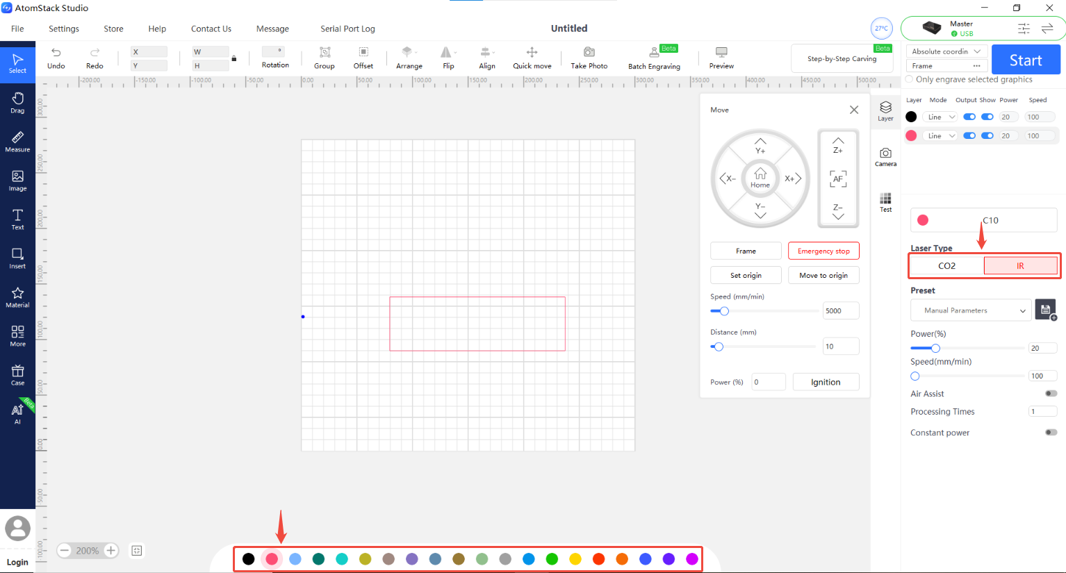
Figure 19
-
After installing the IR laser module, focus calibration must be performed. If the focus distance is inaccurate, the IR laser module will not function properly. Please refer to the “Master Focus Adjustment” section for details.
-
AtomStack Studio supports dual-laser mode, but the CO₂ and IR laser systems must first be calibrated. Please refer to the tutorial video for the calibration procedure.
¶ Master Firmware Update Guide

Please refer to the Master firmware update tutorial video.
Note
- When a new firmware version is available, a firmware update notification will automatically appear when using AtomStack Studio or the mobile app. You may also see a prompt in the firmware version interface asking whether to update or skip the update.
Note: When updating firmware through the software, the USB drive must be inserted into the machine.
- Copy the latest Master firmware file to the root directory of the USB drive using a computer, then insert the USB drive into the machine to start the automatic update process.
Note: The firmware file must be a
.binfile and must not be placed inside a folder.
- If the USB drive included with the machine is damaged, please use another USB drive with a capacity of 32 GB or less.
¶ Master Water Tank Refill and Water Replacement Guide

Please refer to the Master water tank refill and replacement tutorial video.
Note
The water tank must be filled with suitable distilled water, purified water, or high-purity water. The water level should remain between the minimum and maximum level marks.
It is recommended to replace the water in the tank every 30 days.
When the ambient temperature is below 5°C, a non-corrosive antifreeze solution must be added to the water tank. The recommended mixing ratio is as follows:
¶ AtomStack Studio and Mobile App Updates

Please refer to the AtomStack Studio and mobile app update tutorial video.
Note: When a new version is released, the software and mobile app will automatically notify users of the available update when opened. Users may choose whether to update.
¶ Materials Prohibited for Processing with the Master
The following materials must not be processed:
-
PVC (releases chlorine gas)
-
Chlorine-containing plastics
-
Metals with unknown coatings
-
Highly reflective mirror-like materials (laser reflections may damage the laser system)
Note: When processing unknown materials, it is recommended to perform a low-power test first.
¶ Reference Tables
| Operating environment temperature | Antifreeze-to-water ratio |
|---|---|
| -45℃~-42℃ | 6:4(60% antifreeze and 40% water) |
| -35℃~-32℃ | 5:5 (50% antifreeze and 50% water) |
| -25℃~-22℃ | 4:6 (40% antifreeze and 60% water) |
| -15℃~-12℃ | 3:7 (30% antifreeze and 70% water) |
| -5℃~0℃ | 2:8 (20% antifreeze and 80% water) |
| Minimum operating temperature | Antifreeze-to-water ratio |
|---|---|
| -45℃~-42℃ | 6:4 (60% antifreeze and 40% water) |
| -35℃~-32℃ | 5:5 (50% antifreeze and 50% water) |
| -25℃~-22℃ | 4:6 (40% antifreeze and 60% water) |
| -15℃~-12℃ | 3:7 (30% antifreeze and 70% water) |
| -5℃~0℃ | 2:8 (20% antifreeze and 80% water) |