¶ K2 Pro Troubleshooting
Step-by-step checks for power, laser output, homing, connection, focus, camera, flame alarm, and air assist issues.
Jump to your problem
- Quick Troubleshooting Table
- Unable to Power On Normally
- Laser Protective Window or Focusing Lens Contamination
- Insufficient Laser Cutting Power
- No Laser Output
- Homing Failure
- Computer Cannot Connect to the Machine
- Mobile App Cannot Connect to the Machine
- Auto Focus Failure
- During Auto Focus, the Laser Does Not Rise After Coming into Contact with the Material Surface
- Stopping During Engraving
- “USB Drive Not Inserted” Message When Engraving via Wi-Fi
- Unable to Operate Properly, with the Message “Limit Switch Triggered” or “Travel Exceeded”
- The Software Displays “Engraving Area Exceeded”
- Distorted Engraving Output
- Engraved Output Is Reversed or Mirrored
- The Red Crosshair Position Does Not Coincide with the Laser Engraving Position
- Camera Not Working Properly
- Large Errors When Using the Camera
- Abnormal X-Axis or Y-Axis Movement
- Engraved Lines Are Too Thick
- Cut Lines Are Yellow or Black, and the Material Cannot Be Cut Through
- Engraved Lines Are Discontinuous at Corners or Start/End Points (Not Closed)
- Enclosure LED Light Strip Malfunction
- Frequent False “ALARM: 12” Flame Alarm Triggers
- The “ALARM: 12” Flame Alarm Is Triggered but No Water Is Sprayed
- Air Assist Not Working
- Water Drips from the Laser Air Guide After Power-On
- Laser Power Decreases and the Laser Housing Becomes Very Hot After a Period of Engraving
- The Laser Fan Does Not Rotate
- Smoke Inside the Enclosure Cannot Be Exhausted in Time and Escapes Through the Door Gap
- The Image Is Reversed or Mirrored When Using the Rotary Attachment
- What Should I Do If the Timing Belt Is Broken or Damaged?
- AtomStack Studio Software and Mobile App Updates
- Engraver Firmware Update
- Alarm Message Descriptions and Handling Methods
¶ Quick Troubleshooting Table
| Problem | Priority Checks |
|---|---|
| Unable to power on | Check the power supply and power switch. Confirm whether there is a “beep” sound when the mainboard starts up. |
| Insufficient power | Check the focus distance, parameters, processing material, protective window and focusing lens, and measure the voltage. |
| No laser output | Check the software parameters and cable connections. Measure the voltage of the cable connection or check the status of the indicator light on top of the laser source. |
| Reset failure | Confirm that the physical securing modules have been removed. Check the mechanical structure and limit switches, and confirm that the movement direction is correct. |
| Unable to connect to the computer | Confirm that the machine is powered on properly and connected correctly. Confirm that the serial port driver is installed and that the software settings are correct (LightBurn). |
| Autofocus failure | Confirm that the upper and lower limit switches are functioning properly and can contact the material surface. Confirm that the Z-axis motor moves normally. |
| Alarm: USB flash drive not inserted | Confirm that the USB flash drive is inserted, functions properly for reading and writing, has a capacity of 16 GB or less, and is formatted as FAT32. |
| Image distortion | Adjust the mechanical structure and restore the factory settings. |
| Camera not working | Confirm the connection method, ensure that the required permissions are enabled, and confirm that the cable connection is secure. |
| Red crosshair and laser spot do not overlap | Recalibrate the camera. |
¶ Unable to Power On Normally
After turning on the power switch, troubleshoot the issue step by step according to the indicator light status.
After turning on the power switch, none of the indicator lights come on.
① Check the Power Supply
- Check the cables:
Check whether the connection between the adapter and power cord is loose, and whether the power outlet is supplying power properly. You can use another electrical appliance to test the power outlet.
- Check the adapter indicator light:
- Solid green: Indicates that the output is normal.
- Off or flashing alternately: Disconnect the adapter from the laser engraver and check whether the adapter indicator light turns solid green. If the green light turns on normally after disconnection, the adapter is functioning properly, and the laser engraver may have a short circuit. If the indicator light remains abnormal, the adapter may be faulty.
- Measure the output voltage:
If you have a multimeter, set it to the DC voltage range and measure whether the adapter output is 24 V, as shown in Figure 14.
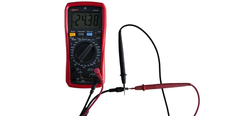
Figure 14
Short-Circuit Troubleshooting Tip: If you suspect a short circuit, disconnect all cables from the mainboard and then power on the machine for testing.
- If the issue persists after disconnecting all cables, the mainboard may be faulty.
- If the machine powers on normally after disconnecting all cables, reconnect the cables for each accessory one by one to identify the accessory causing the short circuit.
② Check the Power Switch
Refer to the K2 Pro Power Switch Troubleshooting and Replacement Video and follow the steps below:
- Disconnect the adapter: Unplug the adapter cable to ensure that all operations are performed safely.
- Remove the cover plate: From the inside front of the machine enclosure, remove the 4 screws securing the cover plate, then remove the cover plate.
- Loosen the cable tie: Use a tool to loosen the cable tie securing the wires so that the switch cable returns to its original length.
- Remove the switch: Use a screwdriver to press the clips on both sides of the switch from the inside, then push the switch outward.
- Bypass the switch: Disconnect the 3 wires from the switch using a screwdriver. Short-circuit the two thickest wires to establish a connection, as shown in Figure 15.
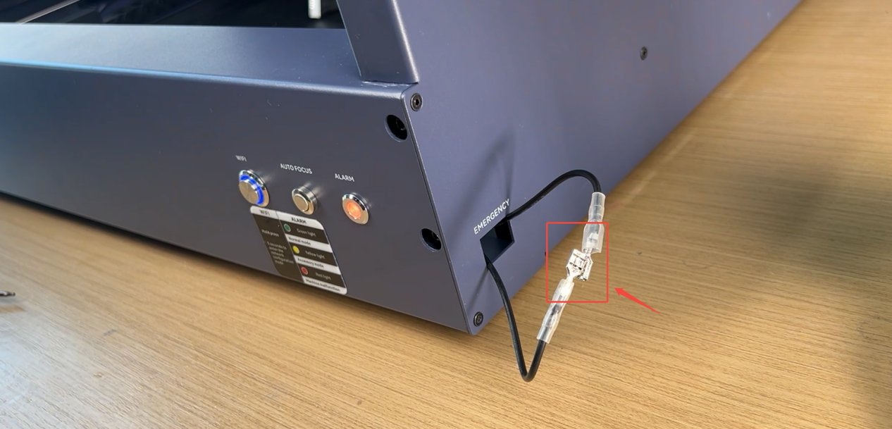
Figure 15
- Power-on test: Connect the adapter output to the “POWER” port of the laser engraver and check whether the machine starts normally. If the machine powers on normally after bypassing the switch, the power switch is faulty.
The Indicator Lights Turn On After Powering On, but the Machine Cannot Be Used
Confirm whether you hear a “beep” sound when the machine starts:
① A “beep” sound is heard:
Check the color of the laser engraver's “ALARM (Status Indicator)”.
If it is red, the machine is in an alarm state. Connect the machine to the software to view the alarm information, then troubleshoot according to the displayed message.
② No “beep” sound is heard:
This indicates that the mainboard has not started normally. Follow the steps below to troubleshoot:
- Connect the machine: Use a Type-C cable to connect the laser engraver to a computer.
- Enable Developer Mode: Open the AtomStack software, click “Settings” in the navigation bar, and click the number displayed under “Version” more than 7 times consecutively. “Serial Port Log” will then appear in the navigation bar as a developer mode option.
- Check the code: Click “Serial Port Log” and check whether the code window continuously outputs garbled characters, as shown in Figure 16.
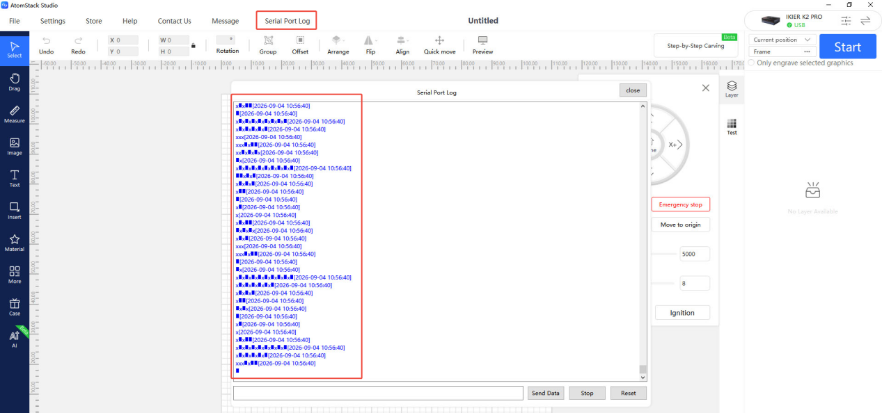
Figure 16
- Analyze the result: If garbled characters are continuously output, the mainboard firmware may be abnormal. If no garbled characters are output, the mainboard may be faulty.
3. Contact Customer Service
If none of the above steps resolves the issue, send the following information to customer service:
- A video showing the problem.
- A description of the troubleshooting steps already performed. If garbled characters appear, provide a screenshot of the garbled characters.
- A photo of the Serial Number on the back of the machine, as shown in Figure 17.
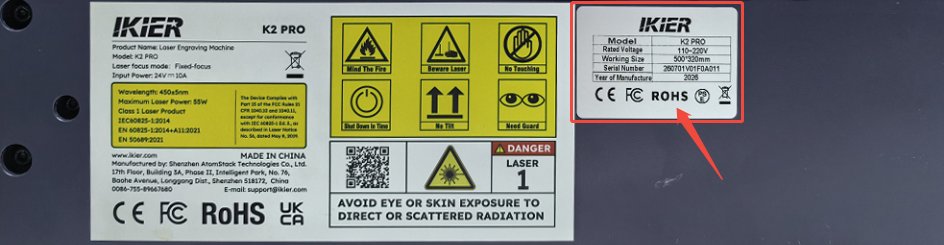
Figure 17
4. Accessory Replacement References
- If the mainboard needs to be replaced, refer to the K2 Pro Mainboard Replacement Video.
- If the power switch needs to be replaced, refer to the K2 Pro Power Switch Troubleshooting and Replacement Video.
¶ Laser Protective Window or Focusing Lens Contamination
Refer to the K2 Pro Laser Cleaning Video and follow the steps below.
1. Cleaning Tools
- Lint-free cloth.
- Anhydrous ethanol (purity of 99% or higher is recommended).
- L2.0 hex key.
2. Cleaning Steps
① Remove the Laser
- Turn off the power: Before removing the laser, turn off the laser engraver to ensure safe operation.
- Disconnect the connections: Gently pull out the side cable and bottom air-assist hose along the direction of the connectors. Do not pull forcefully to prevent loose cable connectors, hose damage, or internal wire breakage.
- Remove the retaining screw: Unscrew the knurled screw on the top of the laser. Keep the laser steady during removal to avoid damaging the threads.
- Remove the laser: Support the laser body with both hands and carefully remove it. Place it on a clean, dedicated, static-safe work surface to prevent impact or damage.
② Clean the Laser Housing
Use a lint-free cloth moistened with anhydrous ethanol to wipe away stains and dust from the surface of the laser.
③ Remove the Air Hood
Use an L2.0 hex key to loosen the set screw on the side of the air duct cover, then gently remove the air hood.
④ Clean the Protective Window
- Remove: Turn the protective window counterclockwise until it can be removed.
- Clean: Apply a small amount of anhydrous ethanol to a lint-free cloth. Wipe the window in a spiral motion from the center outward, gently wiping in one direction. Avoid rubbing back and forth, as this may cause scratches.
⑤ Clean the Air Hood
Use a lint-free cloth moistened with anhydrous ethanol to clean oil and dust from the tip, interior, and air vents of the air hood. Make sure the laser path is not obstructed and the airflow is not blocked.
3. Contact Customer Service
If the protective window or focusing lens has stains that cannot be removed or is damaged, send the following information to customer service:
- Clear photos showing the stains that cannot be removed or the damage.
- A photo of the laser's laser-engraved code, as shown in Figure 18.
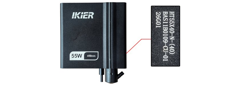
Figure 18
4. Precautions
- Cleaning is required after every 4 hours of cumulative operation to prevent the protective window from being damaged by contaminants burning onto the surface.
- If the protective window is found to be damaged, stop using the machine immediately. Replace the protective window before continuing to use the machine.
Note: Damage to the focusing lens or other optical components caused by contamination, burning, or cracking due to failure to clean the protective window at the specified frequency is not covered by the warranty.
- Two protective window glass pieces are included as spare parts with the machine when shipped from the factory. If you have used both, replacement glass can be purchased from the official website.
¶ Insufficient Laser Cutting Power
Follow the steps below to troubleshoot the issue one by one:
1. Check the Focus Distance
After placing a new material, perform autofocus first. You can also manually adjust the distance. The optimal focus distance is 40 mm.
2. Check the Software Parameters
Different materials require corresponding processing parameters. Refer to the parameter table to confirm that the set power, speed, and speed unit are correct.
How to View the Parameter Table:
- Scan the QR code on the machine.
- Check the included USB flash drive.
- Contact customer service.
3. Check the Material Batch
Different batches of materials may produce different cutting results due to variations in the manufacturing process. It is recommended to:
- Use materials from the same batch for comparison testing.
- Alternatively, cut A4 paper to determine whether the laser power has noticeably decreased.
Recommended Parameters for Cutting A4 Paper: 40% power, 5000 mm/min speed.
4. Check Whether the Air Hood Is Obstructed
Remove the laser and check whether the air vents of the air hood are blocked or obstructed by dirt. If cleaning is required, refer to the K2 Pro Laser Cleaning Video.
5. Check the Laser Protective Window
A dirty or damaged protective window can significantly affect the laser output power. Refer to the K2 Pro Laser Cleaning Video to check the condition of the protective window. If it is dirty or damaged, clean or replace it promptly.
6. Check the S-Value Max (LightBurn)
The S-Value Max must remain at 1000 (as shown in Figure 19) and must not be changed. Otherwise, it may affect the laser power and service life.
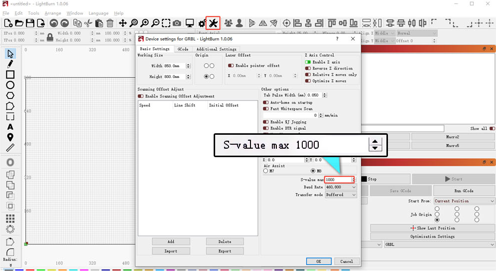
Figure 19
7. Measure the Power Supply Voltage
Voltage or current that is too low can directly affect the laser output power.
- Measure the adapter: Set the multimeter to the DC voltage range and measure whether the adapter output is 24 V.
- Measure the laser cable: Disconnect the laser cable, run a cutting program at 100% power and 1 mm/min, and use a multimeter set to the DC voltage range to measure whether the voltage between pins 2–3 is 24 V and between pins 4–5 is 5 V, as shown in Figure 20. For details, refer to the K2 Pro Laser Cable Voltage Measurement Video.
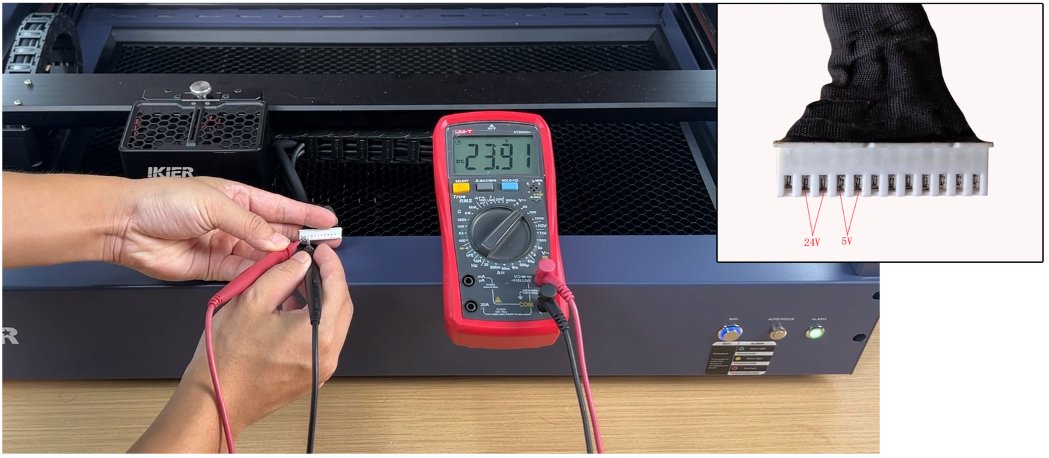
Figure 20
8. Contact Customer Service
If you identify a problem during troubleshooting but cannot resolve it yourself, or if you are still unable to determine the cause of the fault, provide the following information to customer service:
- A4 paper cutting video: Clearly show the focusing process, power/speed settings, cutting process, and final result.
- Description of the troubleshooting steps and results: If you measured the voltage, provide the measurement results.
- Clear photo of the protective window.
- Photo of the laser's laser-engraved code, as shown in Figure 21.
Figure 21
9. Accessory Replacement Reference
- If the protective window needs to be replaced, refer to the K2 Pro Laser Protective Window Replacement Video.
¶ No Laser Output
Follow the steps below to troubleshoot the issue one by one:
1. Check the Software Settings
① Check the Processing Parameters
Different materials require corresponding processing parameters. Refer to the parameter table to confirm that the set power, speed, and speed unit are correct.
How to View the Parameter Table:
- Scan the QR code on the machine.
- Check the included USB flash drive.
- Contact customer service.
② Confirm That Laser Output Is Enabled
The Laser Output option in the software must be enabled, as shown in Figure 22.
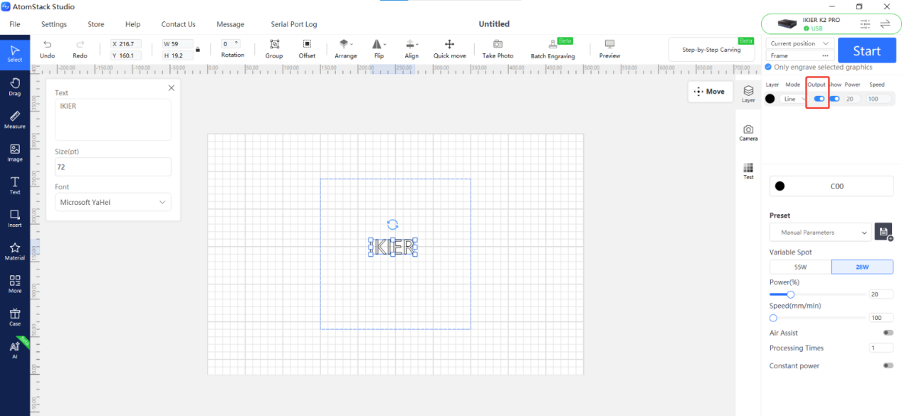
Figure 22
③ Confirm That the S-Value Max Has Not Been Changed (LightBurn Only)
The S-Value Max must remain at 1000 (as shown in Figure 23) and must not be changed. Otherwise, it may affect laser output and service life.
Figure 23
2. Check the Laser Cable
Turn off the power, disconnect the laser cable, and carefully check the cable connector for damage or other abnormalities. If no abnormalities are found, reconnect the cable and power on the machine to test again.
3. Check the Laser Cable Voltage
Insufficient voltage can directly affect the laser power.
- Measure the adapter: Set the multimeter to the DC voltage range and measure whether the adapter output is 24 V.
- Measure the laser cable: Disconnect the laser cable, run a cutting program at 100% power and 1 mm/min, and use a multimeter set to the DC voltage range to measure whether the voltage between pins 2–3 is 24 V and between pins 4–5 is 5 V, as shown in Figure 24. If the measured values are abnormal, continue troubleshooting according to the following steps. For details, refer to the K2 Pro Laser Cable Voltage Measurement Video.
Figure 24
4. Check the Status of the Indicator Lights on Top of the Laser
There are two indicator lights on the top of the laser, near the retaining screw. The status of these indicator lights can be used to determine the cause of the issue.
① Both the Red and Green Lights Are On
This indicates that the laser is receiving power properly and that the driver board output is normal. The laser should be emitting light at this time.
If the laser is not emitting light, open the driver board and check whether the laser diode cable (as shown in Figure 25) is loose or disconnected. Disconnect it and reconnect it securely, then test again. If the laser still does not emit light, the laser diode is considered faulty. For removal instructions, refer to the K2 Pro Laser Driver Board Replacement Video.
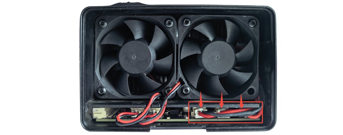
Figure 25
② Only the Red Light Is On
This indicates that the driver board is receiving power normally, but its output is abnormal. Follow Step (3), “Check the Laser Cable Voltage,” to measure the voltage between pins 4–5:
- If the voltage is approximately 5 V, the mainboard and connection cable are functioning normally. Disconnect the laser diode cable from the driver board, then start the engraving operation again and determine the cause based on the resulting behavior.
| Green Indicator Status | Faults |
|---|---|
| On | Laser Diode Failure |
| Off | Driver Board Failure |
- If the voltage is approximately 0 V, check whether the cable on the mainboard is loose or disconnected. If no abnormality is found, the mainboard or connection cable is considered faulty.
③ Neither Light Is On
This indicates abnormal power supply through the connection cable. Follow Step (3), “Check the Laser Cable Voltage,” to measure the voltage between pins 2–3 and pins 4–5:
- If the voltage between pins 2–3 is approximately 24 V and the voltage between pins 4–5 is approximately 5 V, the mainboard and connection cable are functioning normally, and the driver board is considered faulty.
- If either voltage is approximately 0 V, check whether the cable on the mainboard is loose. If no abnormality is found, the mainboard or connection cable is considered faulty.
5. Contact Customer Service
If you identify a problem during troubleshooting but cannot resolve it yourself, or if you are still unable to determine the cause of the fault, provide the following information to customer service:
- Troubleshooting video: Clearly show the power/speed settings, the engraving or cutting process after starting the operation, and the status of the indicator lights on top of the laser.
- Description of the troubleshooting steps and results: If you measured the voltage, provide the measurement results.
- Photo of the machine Serial Number, as shown in Figure 26.
Figure 26
- Photo of the laser's laser-engraved code, as shown in Figure 27.
Figure 27
6. Accessory Replacement References
- If the mainboard needs to be replaced, refer to the K2 Pro Mainboard Replacement Video.
- If the connection cable needs to be replaced, refer to the K2 Pro Connection Cable Replacement Video.
- If the driver board needs to be replaced, refer to the K2 Pro Laser Driver Board Replacement Video.
¶ Homing Failure
Follow the steps below to troubleshoot the issue one by one:
1. Confirm That the Securing Modules Have Been Removed
The X-axis is locked during shipment. After receiving the machine, remove the two securing modules used to secure both ends of the X-axis according to the instructions in the user manual. Make sure that the X-axis can slide freely.
2. Confirm That the Laser Is Not Hitting the Frame
During the reset process, check whether the laser is making contact with the frame. If it is, reinstall the laser according to the Laser Module Replacement Guide section.
If the laser is hitting the frame, the Y-axis limit switch cannot be triggered, resulting in reset failure.
3. Confirm That the X-Axis Is Parallel to the Frame
Use a ruler to measure the distances from both ends of the X-axis to the upper and lower frames and check whether they are equal. If the distances are not equal, refer to the K2 Pro X-Axis Leveling Adjustment Video for adjustment instructions.
4. Check the Movement of Each Axis
Observe the movement of each axis during the homing. If any abnormality is found, troubleshoot according to the following conditions:
① Homing in the Wrong Direction
- Movement direction is reversed: Click the direction control buttons in the software and check whether the movement direction is abnormal. If the movement direction is reversed, restore the factory settings or modify the corresponding axis's
$3value in Machine Settings in LightBurn, as shown in Figure 28.
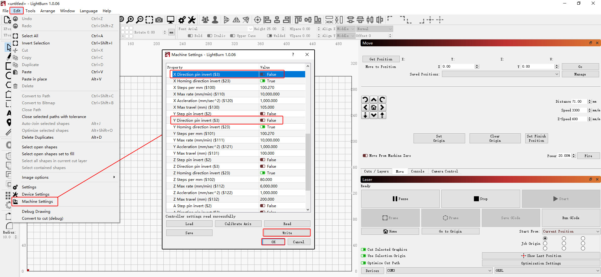
Figure 28
- Movement direction is normal, but the reset direction is reversed: Restore the factory settings or modify the corresponding axis's
$23value in Machine Settings in LightBurn, as shown in Figure 29.
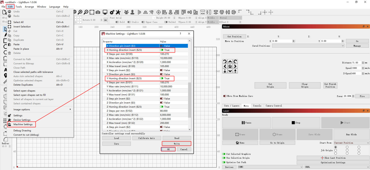
Figure 29
② Abnormal X-Axis or Y-Axis Movement
- Check the motor cable: Carefully check the motor cable for damage. Disconnect it and reconnect it securely, then test again.
- Swap the motor cables: Follow the K2 Pro Motor Cable Swapping Video to connect the Y-axis motor cable to the X-axis motor, then determine the cause of the fault based on the resulting behavior.
| Fault Symptoms | After Swapping | Diagnosis |
|---|---|---|
| X-axis normal, Y-axis abnormal | X-axis abnormal | Mainboard or Y-axis motor cable fault |
| X-axis normal, Y-axis abnormal | X-axis normal | Y-axis motor fault |
| X-axis abnormal, Y-axis normal | X-axis normal | Mainboard or X-axis motor cable fault |
| X-axis abnormal, Y-axis normal | X-axis abnormal | X-axis motor fault |
5. Confirm That All Limit Switches Are Functioning Properly
Refer to the K2 Pro XYZ Limit Switch Verification and Troubleshooting Video. Manually press the two front and rear limit switches on the Y-axis (left axis) and the two limit switches at both ends of the X-axis.
Check whether each switch triggers the corresponding prompt and produces a “beep-beep” sound. If a limit switch cannot be triggered, check the following:
- Check the appearance of the limit switch: Carefully inspect the limit switch for any damage, such as a broken spring plate or detached terminal.
- Check the cable connections: Check whether the cables at the limit switch and mainboard are loose or disconnected.
- Measure the cable voltage: Disconnect the cables at the limit switches one by one and use a multimeter set to the DC voltage range to measure the cable voltage, as shown in Figure 30.
| Voltage Reading | Diagnosis Result |
|---|---|
| Roughly 0 V | Limit Switch Cable Fault |
| Roughly 3.3 V | Limit Switch Fault |
If none of the limit switches can be triggered, the mainboard firmware may be abnormal. Contact customer service for assistance according to Step (8).
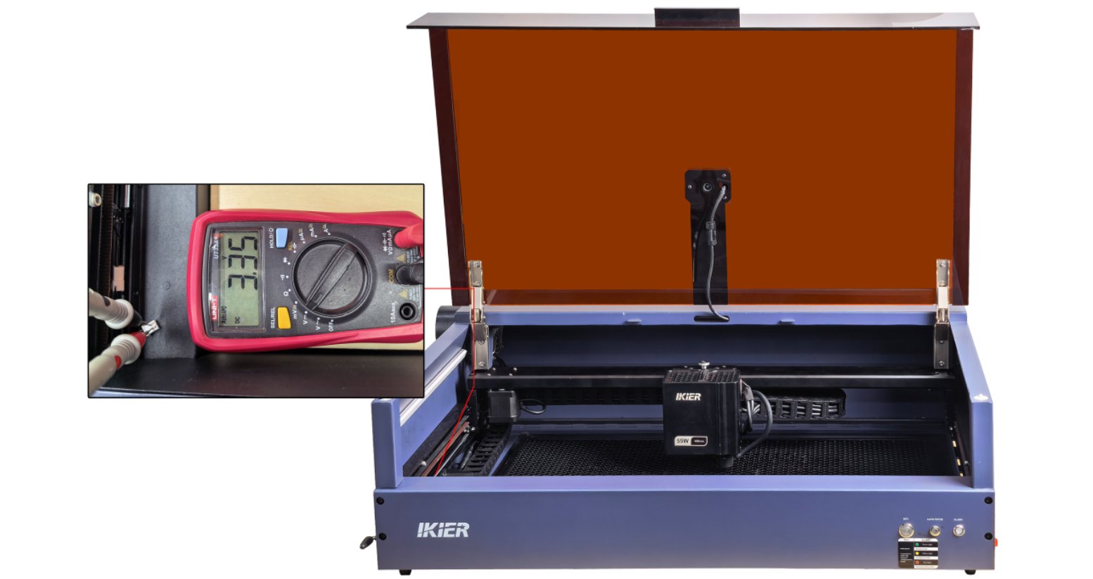
Figure 30
6. Restore Factory Settings
If none of the above steps resolves the issue, refer to the K2 Pro Factory Reset Video and follow the steps below:
① AtomStack Studio
- Click the “Settings” menu in the navigation bar and find “Version: V*.*.*” in the Settings window.
- Click the number after the version number more than 7 times consecutively. The “Serial Port Log” developer mode option will appear in the menu bar.
- Click “Serial Port Log” to enter the interface. A series of execution codes will be displayed in the code box.
- Click “Reset” in the lower-right corner of the interface. If the console displays several reset completion messages and ends with “OK”, the reset is complete.
- Click “Close” in the upper-right corner to exit the interface.
② LightBurn
Select “Console”, enter $RST=* in the code box, and click Send, as shown in Figure 31.
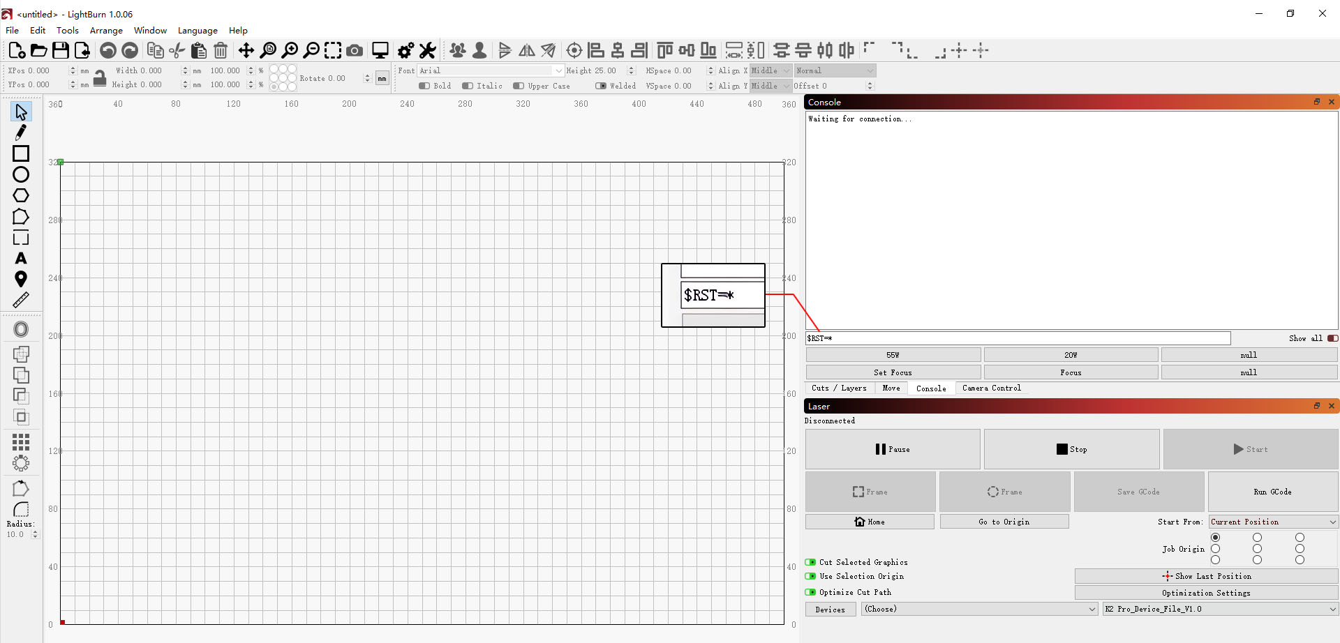
Figure 31
7. Firmware Update
All firmware update methods require a USB flash drive to be inserted as the storage medium. Do not power off the machine or remove the USB flash drive during the update process.
Update Firmware in AtomStack Studio
Open the software and connect the laser engraver. Click the “☰” icon in the upper-right corner of the software interface to enter the Device Information page. The current firmware version can be viewed at the bottom of the page. If an update prompt appears to the right of the version, click it to update the firmware, as shown in Figure 32.
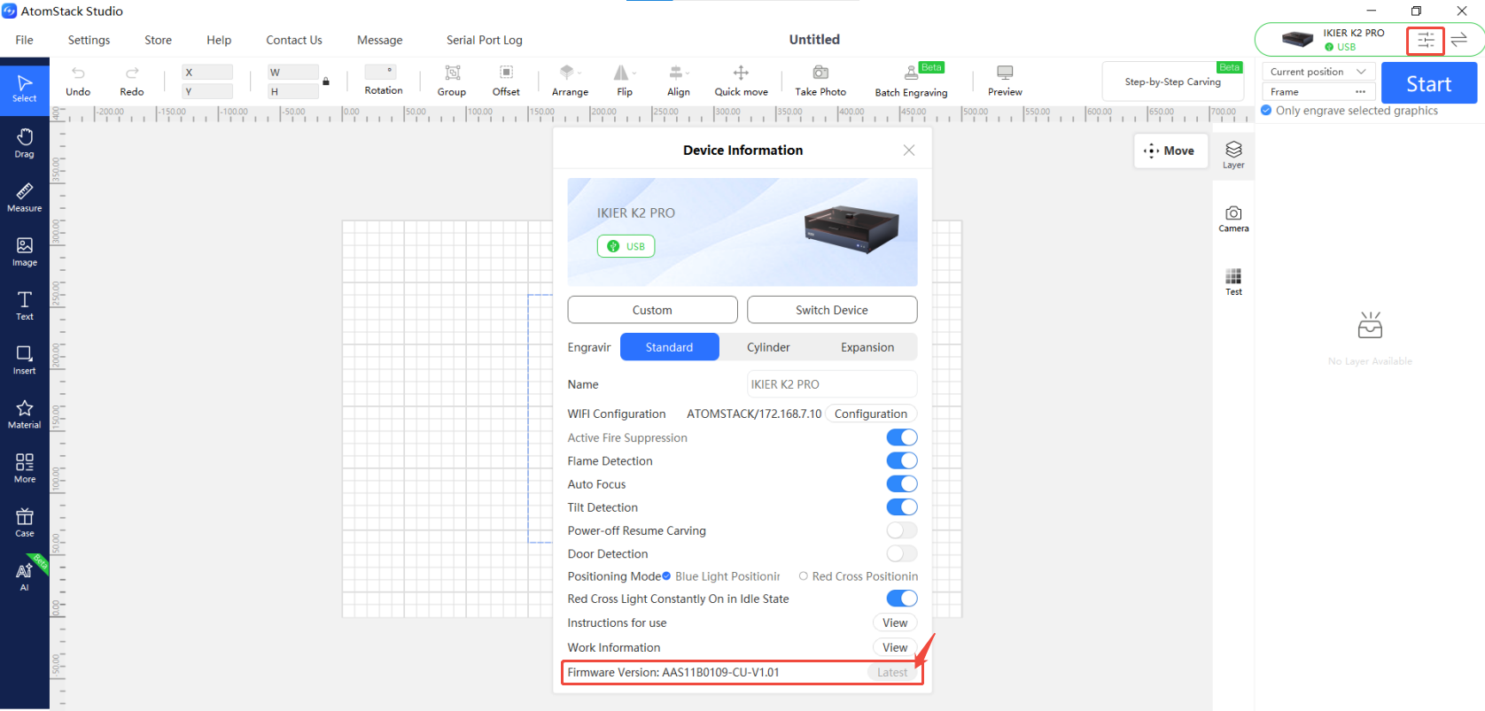
Figure 32
Update Firmware in the AtomStack App
Open the app and connect the laser engraver. Tap “Settings” below the model name to enter the Device Settings page. The current firmware version and the option to update to the latest firmware can be viewed at the bottom of the page, as shown in Figure 33.
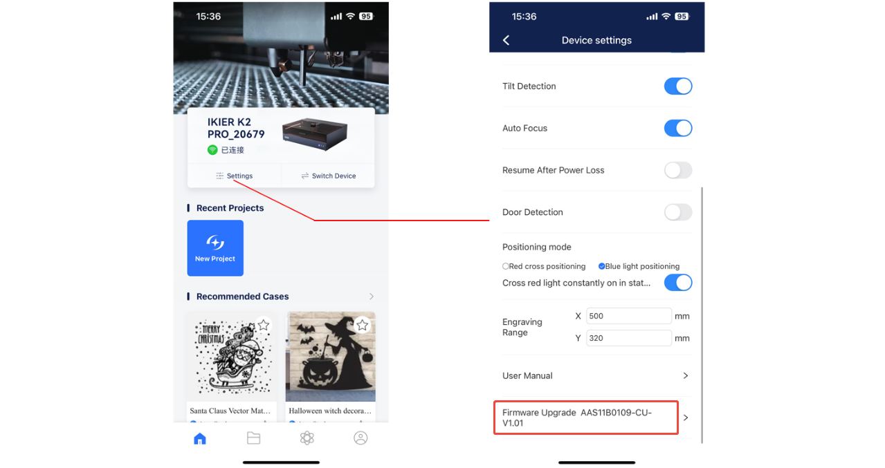
Figure 33
Update Firmware Using a USB Flash Drive
If the firmware cannot be updated using either of the above methods, please provide customer service with a screenshot of the laser engraver's current firmware version and a photo of the laser engraver's Serial Number to obtain the latest firmware. Follow the steps below to update the firmware:
- Insert the USB flash drive into a card reader and connect it to a computer.
- Copy the new firmware file (.bin file) to the root directory of the USB flash drive. Do not place it in a folder.
- Insert the USB flash drive into the laser engraver and power it on. The device will update automatically and emit a “beep-beep” sound.
- Wait until the beeping stops, then restart the laser engraver.
8. Contact Customer Service
If a problem is identified during troubleshooting but cannot be resolved independently, or if the cause of the fault cannot be determined, please provide the following information when contacting customer service:
- Fault video: Clearly show the complete reset process and the manual inspection of each limit switch.
- Screenshot of the firmware version.
- Troubleshooting steps completed and the corresponding results.
- Photo of the machine Serial Number, as shown in Figure 34.
Figure 34
9. Replacement Reference for Components
- To replace the mainboard, refer to the K2 Pro Mainboard Replacement Video.
- To replace the mainboard connection cable or limit switch cable, refer to the K2 Pro Connection Cable Replacement Video.
- To replace a limit switch, refer to the K2 Pro XYZ Limit Switch Replacement Video.
- To replace a motor, refer to the K2 Pro X/Y/Z-Axis Motor Replacement Video.
¶ Computer Cannot Connect to the Machine
Please follow the steps below one by one to troubleshoot the issue:
1. Confirm that the machine has powered on properly
① After powering on, check whether you hear the “beep” sound indicating that the mainboard has started up normally.
② Check whether the panel indicator lights and LED light strip are lit normally.
2. Confirm that the Type-C cable is connected correctly
① When using a Type-C cable, the C connector must be plugged into the “COMPUTER” port on the laser engraver (see the Unboxing and Installation section for details).
② Pay attention to the operating system:
- Windows: Either the C or A connector of the Type-C cable can be connected to the computer's USB port. For desktop computers, connecting to a USB port on the back of the computer case is recommended.
- macOS: A hub/docking station (as shown in Figure 35) is required to connect the A connector of the Type-C cable to the computer.
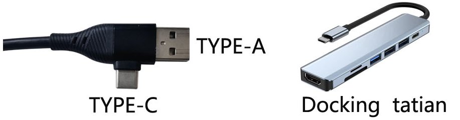
Figure 35
3. Check whether the “COMPUTER” port is damaged
Carefully check the “COMPUTER” port on the laser engraver for any damage or foreign objects blocking the port.
4. Confirm that the serial port driver is installed
The serial port driver must be installed when using the machine for the first time. Download the driver from the links below:
- Windows driver: Download Windows Driver
- macOS driver: Download macOS Driver
Verification: In Device Manager → Ports (COM & LPT) on the computer, check whether a serial port such as CH340 is displayed, as shown in Figure 36.
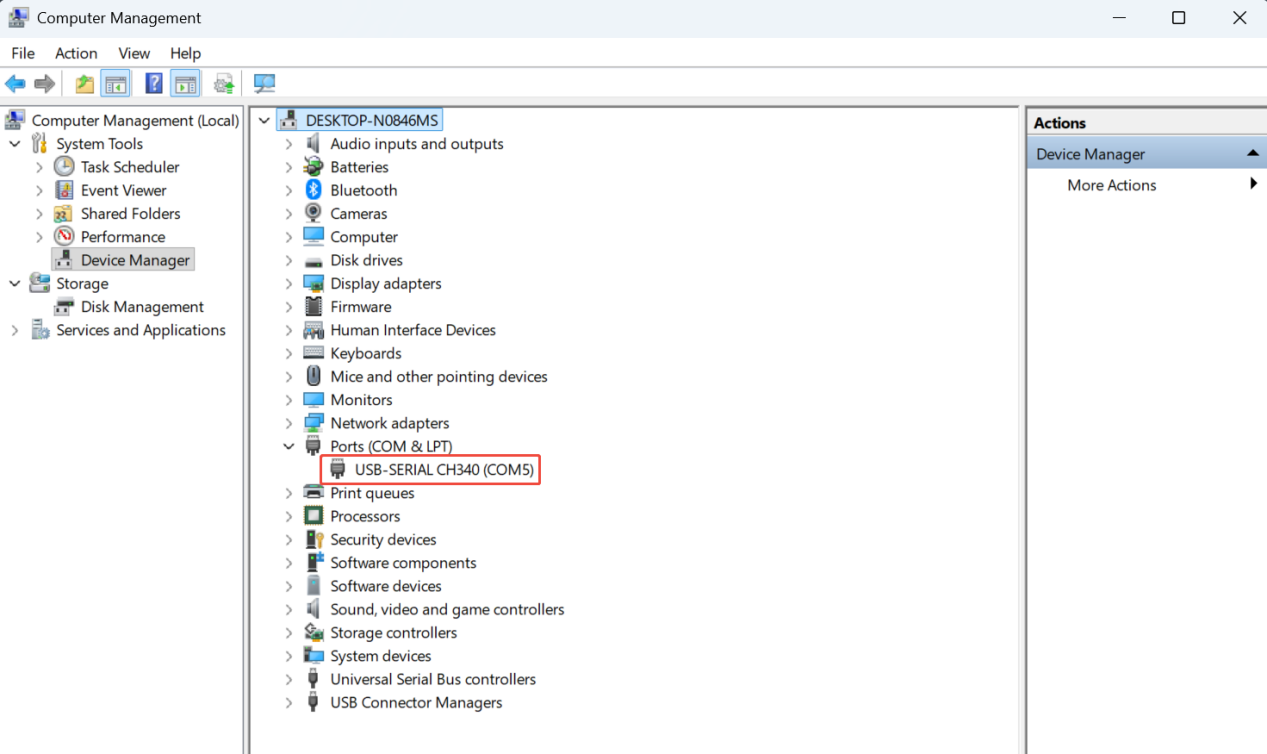
Figure 36
5. Check the software version
- AtomStack Studio: Update to the latest version.
- LightBurn: Version 1.7.08 is recommended for optimal stability.
6. Confirm that the software is configured correctly
① AtomStack Studio
The software automatically identifies the machine model, so no additional configuration is required.
② LightBurn
Modify the following settings:
- Manually add a “GRBL” controller or import the K2 Pro configuration file.
- Select the correct COM port and set the baud rate to 460800, as shown in Figure 37.
- Set the engraving area to 500 mm × 320 mm.
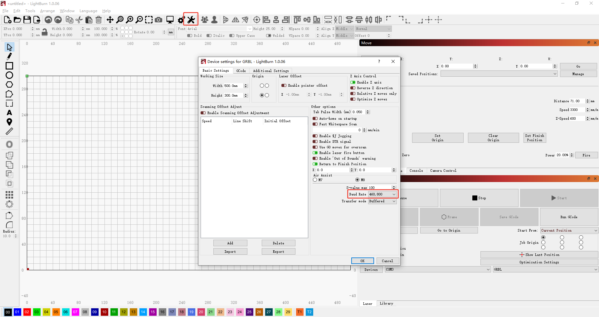
Figure 37
For instructions on importing the configuration file, refer to the K2 Pro Computer Connection Video.
7. Try a different computer and Type-C cable
- Try a different USB port on the computer. For desktop computers, connecting to a USB port on the back of the computer case is recommended.
- Replace the Type-C cable with one that supports data transfer. Do not use a cable that supports charging only.
- If possible, try another computer to rule out compatibility issues with the USB port or operating system of the current computer.
8. Contact Customer Service
If a problem is identified during troubleshooting but cannot be resolved independently, or if the cause of the fault cannot be determined, please provide the following information when contacting customer service:
- Fault video: Clearly show the complete connection process, including how the Type-C cable is connected, how the serial port is checked, how the driver is installed, etc.
- Troubleshooting steps completed and the corresponding results.
- Photo of the machine Serial Number, as shown in Figure 38.
Figure 38
9. Replacement Reference for Components
- To replace the mainboard, refer to the K2 Pro Mainboard Replacement Video.
¶ Mobile App Cannot Connect to the Machine
Please follow the steps below one by one to troubleshoot the issue:
1. Confirm that Wi-Fi mode is enabled
Press and hold the “Wi-Fi” button for more than 5 seconds to enter Wi-Fi configuration mode.
2. Confirm the router frequency band
The router must support the 2.4 GHz frequency band. When connecting, select a 2.4 GHz Wi-Fi network. Do not select a 5 GHz network.
3. Confirm that the app connection procedure is correct
Open the app, tap “Add Device” on the home page, and follow the on-screen instructions to complete the device connection.
For connection instructions, refer to the K2 Pro Mobile App Connection Video.
4. Confirm that the Wi-Fi connection is not being used by another device
Make sure the laser engraver's Wi-Fi connection is not being used by another phone or software.
5. Restart the app and laser engraver
Turn off the laser engraver and exit the app, then turn the laser engraver back on and reopen the app to try connecting again.
6. Confirm that the app is up to date
Open the app, tap the “Profile” icon in the lower-right corner, then go to “Profile” → “Settings” → “About ATOMSTACK” to view the version information, as shown in Figure 39. If an update is available, complete the update first.
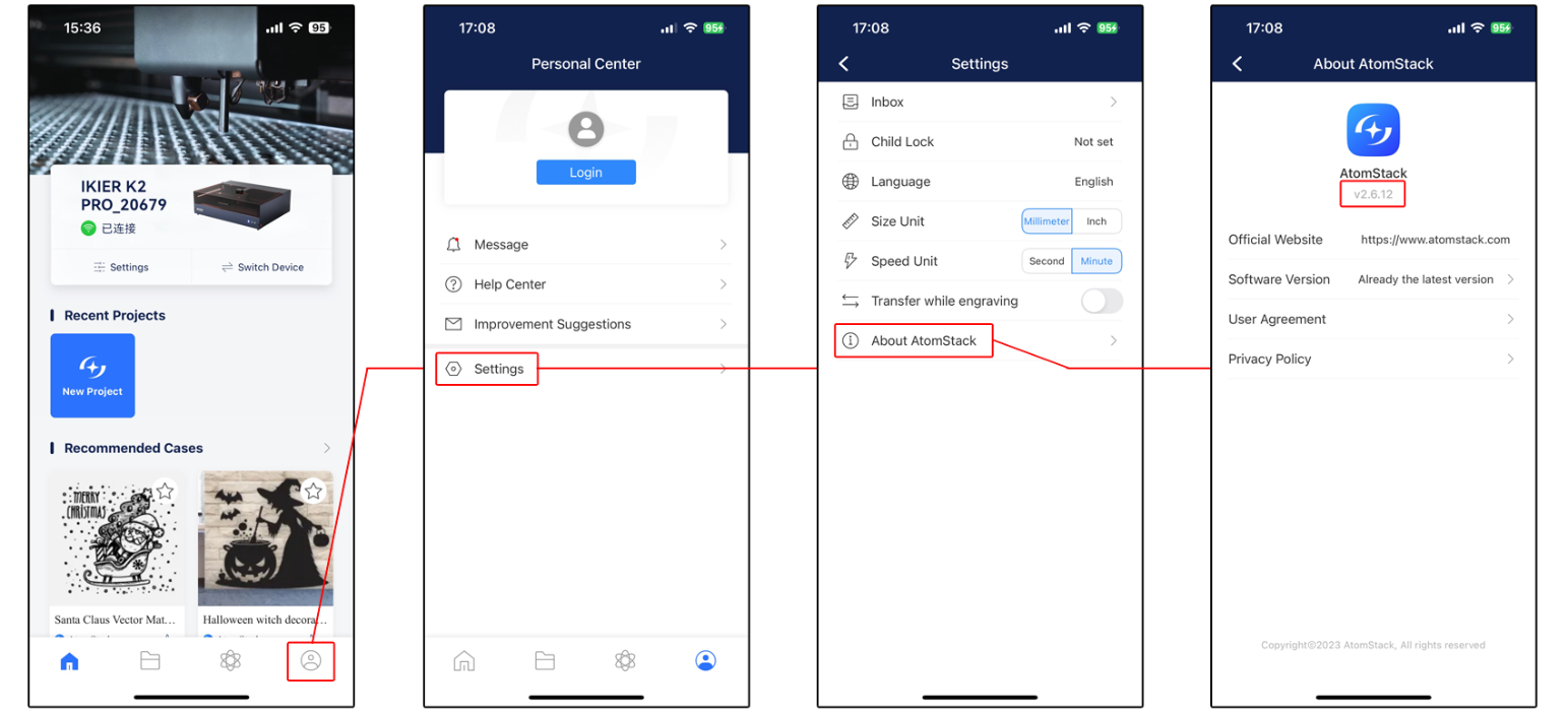
Figure 39
7. Try connecting with another phone
If possible, use another phone to try connecting to rule out compatibility issues with the current phone.
8. Contact Customer Service
If the connection still fails after completing all the troubleshooting steps above, please provide the following information to customer service:
- Operation video: Record the complete connection process, including the operations performed on the phone screen and the status of the machine.
- App version.
- Laser engraver firmware version: Connect the machine to a computer using the computer client, then view the firmware version on the Device Information page, as shown in Figure 40.
Figure 40
- Photo of the machine Serial Number, as shown in Figure 41.
Figure 41
9. Replacement Reference for Components
- To replace the mainboard, refer to the K2 Pro Mainboard Replacement Video.
¶ Auto Focus Failure
Carefully observe the status of the Z-axis and follow the steps below one by one to troubleshoot the issue:
You can refer to the K2 Pro XYZ Limit Switch Verification and Troubleshooting Video for the relevant procedures.
1. The Z-axis does not stop when it reaches the highest position
Manually turn the knob to move the Z-axis to its highest position and check whether the upper limit switch can be triggered normally. A “beep-beep” sound will be emitted when the switch is triggered.
① If the upper limit switch cannot be triggered normally
Refer to the K2 Pro XYZ Limit Switch Replacement Video and perform the following checks:
- Check whether the upper limit switch cable is loose.
- Check whether the upper limit switch is damaged.
- Check whether any wires are exposed from the X-axis cable chain.
- Measure the voltage of the upper limit switch cable. It should be approximately 3.3 V, as shown in Figure 42. If the measured voltage is approximately 0 V, the mainboard or connection cable is faulty.
Figure 42
② If the upper limit switch can be triggered normally but the auto focus problem persists
Skip directly to Steps (4) and (5) and try restoring the factory settings and updating the firmware.
2. The laser does not stop after the trigger rod contacts the material surface
① The trigger rod does not contact the material
Check whether the trigger rod at the bottom of the laser can contact the material surface, as shown in Figure 43. If it does not, move the laser so that the trigger rod can make proper contact with the material surface.
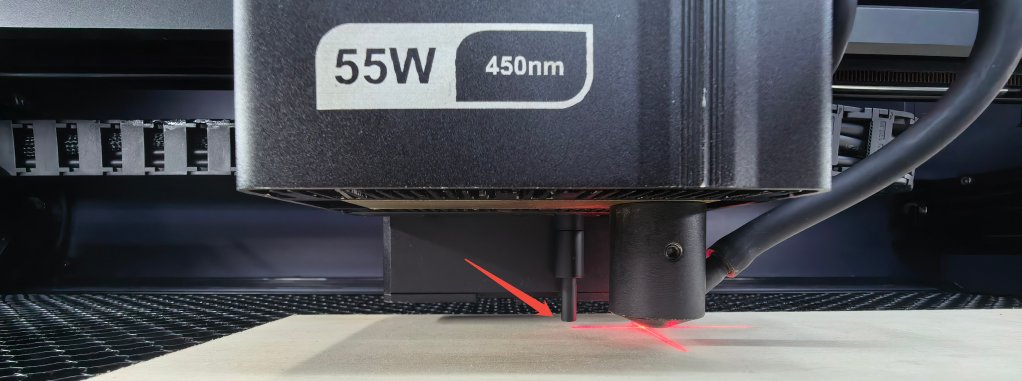
Figure 43
② The material is too soft
Check whether the material is too soft. Soft materials may prevent the trigger rod from effectively triggering the lower limit switch, resulting in auto focus failure or an inaccurate focus distance.
③ Check the lower limit switch
Press the trigger rod by hand and determine the result as follows:
- Cannot be triggered (no “beep-beep” sound): The lower limit switch is faulty and the driver board needs to be replaced.
- Trigger rod cannot be pressed: The trigger rod may be stuck. Open the bottom plate of the laser and reinstall the trigger rod.
3. The Z-axis stops after moving a very short distance and makes an abnormal noise
① Check the Z-axis motor cable
Refer to the K2 Pro X/Y/Z-Axis Motor Replacement Video and check whether the Z-axis motor cable is loose or damaged. Disconnect the cable and reconnect it, then test again.
② Adjust the Z-axis lead screw
Remove the entire Z-axis module and check whether the lead screw is bent or deformed. You can also loosen the screws securing the lead screw at the bottom and adjust its position.
If the surface of the lead screw is relatively dry, apply a uniform layer of lubricating grease. For the recommended grease, refer to the Enclosure Interior Maintenance section.
③ Check the Z-axis motor
Refer to the K2 Pro Motor Cable Swapping Video and connect the Y-axis motor cable to the Z-axis motor to check whether the Z-axis motor can operate normally:
- If the fault persists: The Z-axis motor is faulty.
- If the Z-axis operates normally: The mainboard or connection cable is faulty.
4. Restore Factory Settings
If none of the above steps resolves the issue, refer to the K2 Pro Factory Reset Video and follow the steps below:
① AtomStack Studio
- Click the “Settings” menu in the navigation bar and find “Version: V*.*.*” in the Settings window.
- Click the number after the version number more than 7 times consecutively. The “Serial Port Log” developer mode option will appear in the menu bar.
- Click “Serial Port Log” to enter the interface. A series of execution codes will be displayed in the code box.
- Click “Reset” in the lower-right corner of the interface. If the console displays several reset completion messages and ends with “OK”, the reset is complete.
- Click “Close” in the upper-right corner to exit the interface.
② LightBurn
Select “Console”, enter $RST=* in the code box, and click Send, as shown in Figure 44.
Figure 44
5. Firmware Update
All firmware update methods require a USB flash drive to be inserted as the storage medium. Do not power off the machine or remove the USB flash drive during the update process.
① Update Firmware in AtomStack Studio
Open the software and connect the laser engraver. Click the “☰” icon in the upper-right corner of the software interface to enter the Device Information page. The current firmware version can be viewed at the bottom of the page. If an update prompt appears to the right of the version, click it to update the firmware, as shown in Figure 45.
Figure 45
② Update Firmware in the AtomStack App
Open the app and connect the laser engraver. Tap “Settings” below the model name to enter the Device Settings page. The current firmware version and the option to update the firmware can be viewed at the bottom of the page, as shown in Figure 46.
Figure 46
③ Update Firmware Using a USB Flash Drive
If the firmware cannot be updated using either of the above methods, please provide customer service with a screenshot of the laser engraver's current firmware version and a photo of the laser engraver's Serial Number to obtain the latest firmware. Follow the steps below to update the firmware:
- Remove the USB flash drive and connect it to a computer using a card reader.
- Copy the new firmware file (.bin file) to the root directory of the USB flash drive. Do not place it in a folder.
- Insert the USB flash drive into the laser engraver and power it on. The device will update automatically and emit a “beep-beep” sound.
- Wait until the beeping stops, then restart the laser engraver.
6. Contact Customer Service
If a problem is identified during troubleshooting but cannot be resolved independently, or if the cause of the fault cannot be determined, please provide the following information when contacting customer service:
- Fault video: Clearly show the complete process.
- Troubleshooting steps completed and the corresponding results.
- Screenshot of the firmware version.
- Photo of the machine Serial Number, as shown in Figure 47.
Figure 47
7. Replacement Reference for Components
- To replace the mainboard, refer to the K2 Pro Mainboard Replacement Video.
- To replace a limit switch, refer to the K2 Pro XYZ Limit Switch Replacement Video.
- To replace a connection cable, refer to the K2 Pro Connection Cable Replacement Video.
- To replace the lower limit switch, refer to the K2 Pro Laser Driver Board Replacement Video.
¶ During Auto Focus, the Laser Does Not Rise After Coming into Contact with the Material Surface
Please follow the steps below one by one to troubleshoot the issue:
1. Confirm that the trigger rod can contact the material surface
Check whether the trigger rod at the bottom of the laser can contact the material surface, as shown in Figure 48. If it is not in contact with the material, move the laser above the material so that the trigger rod can make proper contact with the material surface.
Figure 48
2. Manually press the trigger rod to test
Press the trigger rod at the bottom of the laser by hand and check whether it triggers the normal prompt (a “beep-beep” sound). Determine the result as follows:
- Cannot be triggered (no “beep-beep” sound): The lower limit switch is faulty and the driver board needs to be replaced.
- Triggers normally (a “beep-beep” sound is heard): First check whether the trigger rod can make proper contact with the material. If there is no abnormality, proceed directly to Step (4).
- Trigger rod cannot be pressed: The trigger rod may be stuck. Open the bottom plate of the laser and reinstall the trigger rod.
3. Move the Z-axis up and down using the software
Use the Z-axis movement buttons in the software to move the Z-axis up and down and check whether it operates normally.
- Operates normally: The Z-axis motor and mechanical structure are functioning normally. The issue may be caused by abnormal firmware. Proceed to Step (5) to restore the factory settings.
- Cannot move upward: The connection cable or mainboard may be faulty.
4. Check the Z-axis Motor
Refer to the K2 Pro Motor Cable Swapping Video and connect the Y-axis motor cable to the Z-axis motor to check whether the Z-axis motor is faulty.
5. Restore Factory Settings
If none of the above steps resolves the issue, refer to the K2 Pro Factory Reset Video and follow the steps below:
① AtomStack Studio
- Click the “Settings” menu in the navigation bar and find “Version: V*.*.*” in the Settings window.
- Click the number after the version number more than 7 times consecutively. The “Serial Port Log” developer mode option will appear in the menu bar.
- Click “Serial Port Log” to enter the interface. A series of execution codes will be displayed in the code box.
- Click “Reset” in the lower-right corner of the interface. If the console displays a reset completion message and ends with “OK”, the reset is complete.
- Click “Close” in the upper-right corner to exit the interface.
② LightBurn
Select “Console”, enter $RST=* in the code box, and click Send, as shown in Figure 49.
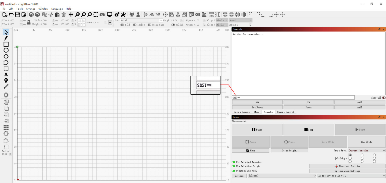
Figure 49
6. Contact Customer Service
If a problem is identified during troubleshooting but cannot be resolved independently, or if the cause of the fault cannot be determined, please provide the following information when contacting customer service:
- Fault video: Clearly show the complete process.
- Troubleshooting steps completed and the corresponding results.
- Screenshot of the firmware version.
- Photo of the machine Serial Number, as shown in Figure 50.
Figure 50
7. Replacement Reference for Components
- To replace the mainboard, refer to the K2 Pro Mainboard Replacement Video.
- To replace a limit switch, refer to the K2 Pro XYZ Limit Switch Replacement Video.
- To replace a connection cable, refer to the K2 Pro Connection Cable Replacement Video.
- To replace the lower limit switch, refer to the K2 Pro Laser Driver Board Replacement Video.
¶ Stopping During Engraving
Please troubleshoot the issue step by step as follows:
1. Check the connection method
It is recommended to connect the machine using a Type-C cable. If the computer is connected via Wi-Fi, data packet loss may cause errors or unexpected interruptions during engraving.
2. Check the software alarm messages
① USB Key not connected
Check whether the USB Key is properly inserted, as shown in Figure 51. Gently move the USB Key and check whether the indicator light turns green.
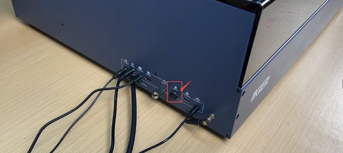
Figure 51
② Abnormal opening of the enclosure
- Confirm that the enclosure door was not opened during engraving.
- Check whether there are any foreign objects obstructing the enclosure door and confirm that the door can close properly.
③ Alarm messages
- ALARM 1: A limit switch has been triggered. Confirm that framing has been performed and that the file size is within the engraving area. If the alarm was triggered abnormally, refer to the K2 Pro XYZ Limit Switch Verification and Troubleshooting Video to check whether each limit switch is functioning properly.
- ALARM 3: This code is usually triggered after clicking Stop to stop engraving. It may also be caused by a false alarm from the software. If the signal was not triggered intentionally, try using different control software or updating the software and then test again.
Recommended control software: LightBurn and AtomStack Studio.
- ALARM 12: Flame alarm. The AtomStack Studio interface will display “Warning! Flame detected”. Once triggered, the machine will automatically stop engraving. If the fire-extinguishing air pump is connected and the water tank has sufficient water, the engraver will automatically spray water to extinguish the fire.
If water is sprayed to extinguish the fire after a flame alarm is triggered, perform the following steps after the fire is extinguished:
- Dry any remaining water: Start a low-power engraving or cutting program and run it for 5 minutes to use the airflow to dry the water remaining inside the hose.
- Clean the protective window and air duct: Refer to the K2 Pro Laser Cleaning Video. Wipe away any water from the surface of the protective window, the focusing lens (do not remove it), and the inside and outside of the air duct.
After each flame alarm is triggered, immediately perform the drying operation described above to prevent water from accumulating and affecting the machine's engraving and cutting performance.
- ALARM 13: Enclosure door open alarm. This may be caused by opening the enclosure door during engraving.
3. Check the Type-C cable connection
If the machine is connected via a Type-C cable, unplug the cable and reconnect it, or try a different USB port on the computer. For desktop computers, it is recommended to use a USB port on the back of the computer.
4. Check the computer system
If you are using Windows 11, do not switch the control software to the background while engraving. Also check whether the COM port sleep function is enabled.
5. Try different control software
Try using different control software. AtomStack Studio or LightBurn is recommended. You can also connect the machine via the mobile app and perform an engraving test to see whether the issue recurs.
6. Replace the power adapter
Replace the power adapter with another DC 24 V 10 A power adapter and test whether the issue recurs.
7. Contact Customer Support
If you identify an issue during troubleshooting but cannot resolve it yourself, or if you are unable to determine the cause of the issue, please provide the following information when contacting Customer Support:
- Video of the issue: If the issue can be easily reproduced, record the entire process.
- Completed troubleshooting steps and results.
- Screenshot of the firmware version.
- Photo of the machine Serial Number, as shown in Figure 52.
Figure 52
8. Reference for accessory replacement
- If the mainboard needs to be replaced, refer to the K2 Pro Mainboard Replacement Video.
- If the limit switches need to be replaced, refer to the K2 Pro XYZ Limit Switch Replacement Video.
¶ “USB Drive Not Inserted” Message When Engraving via Wi-Fi
Please troubleshoot the issue step by step as follows:
1. Confirm that the USB drive is inserted
Check whether a USB drive is inserted into the “USB DRIVE” port on the engraver. If it is already inserted, turn off the engraver, remove the USB drive, then reinsert it and turn the machine back on for testing.
2. Confirm the USB drive capacity
A USB drive with a capacity of 4 GB or 8 GB is recommended. It is recommended not to use one larger than 16 GB. An oversized USB drive may not be recognized by the engraver.
3. Confirm that the USB drive can be read and written normally
After turning off the engraver, remove the USB drive and insert it into a USB port on the computer to check whether the computer can recognize it properly.
- If the computer can recognize the USB drive and read/write to it normally, but the engraver still cannot recognize it, format the USB drive as FAT32 and test again.
- If the computer cannot recognize the USB drive properly, try formatting it as FAT32. If it is still not recognized, the USB drive is considered faulty.
4. Test with another USB drive
Replace the USB drive with another one with a capacity of 16 GB or less and formatted as FAT32, then insert it into the engraver to check whether it can be recognized normally. If it is still not recognized, the mainboard is considered faulty.
5. Confirm that the app has been updated to the latest version
Open the app, tap the icon in the lower-right corner, then go to “Personal Center” → “Settings” → “About ATOMSTACK” to check the version information, as shown in Figure 53. If an update is available, complete the update before testing again.
Figure 53
6. Confirm that the firmware has not been written or modified without authorization
Confirm that no other software has been used to write or modify the firmware. Incorrect firmware writing may cause program errors and prevent the device from operating properly.
Note: If the firmware has ever been modified or written, inform Customer Support proactively.
7. Contact Customer Support
If the issue cannot be resolved after completing all the above steps, please provide the following information when contacting Customer Support:
- Video of the issue: Clearly show the issue, including the software message and the USB drive read/write test on the computer.
- Completed troubleshooting steps and results.
- Screenshot of the firmware version.
- Photo of the machine Serial Number, as shown in Figure 54.
Figure 54
8. Reference for accessory replacement
- If the mainboard needs to be replaced, refer to the K2 Pro Mainboard Replacement Video.
¶ Unable to Operate Properly, with the Message “Limit Switch Triggered” or “Travel Exceeded”
Please troubleshoot the issue step by step as follows:
1. Check the engraving file size
Check whether the current engraving file is completely within the engraving area. Make sure there are no residual graphics or accidentally selected extra patterns outside the engraving area.
2. Check the selected coordinate mode
- Absolute Coordinates: As long as the file is within the engraving area, this alarm will normally not be triggered.
- Current Position: The laser must be moved manually or through the software to a suitable position, leaving sufficient space for the engraving path. Otherwise, the alarm may be triggered.
When using Current Position mode, it is recommended to perform a framing operation before engraving to confirm that the engraving area meets the requirements.
3. Confirm that the movement direction is correct
Click the directional movement buttons in the software and observe whether the movement direction of each axis is abnormal. If an axis moves in the opposite direction, the issue can be resolved by restoring the factory settings or by modifying the corresponding axis $3 value in “Machine Settings” in LightBurn, as shown in Figure 55.
Figure 55
4. Check the software alarm message
- X-axis: Check whether the laser has touched the left or right limit switch (reached the edge).
- Y-axis: Check whether the laser has touched the front or rear limit switch on the right side of the Y-axis (reached the edge).
5. Manually trigger the limit switches for troubleshooting
Refer to the K2 Pro XYZ Limit Switch Verification and Troubleshooting Video. Press the two front and rear limit switches on the Y-axis (left axis) and the two limit switches at both ends of the X-axis one by one.
Check whether the corresponding alarm is triggered normally and whether a “beep-beep” sound is emitted.
6. Check the limit switch wiring
Refer to the K2 Pro XYZ Limit Switch Replacement Video. Check whether the limit switch wires are broken, and also check whether the limit switches are damaged.
7. Restore the factory settings
If the above steps do not resolve the issue, refer to the K2 Pro Factory Reset Video and follow the steps below:
① AtomStack Studio
- Click the “Settings” menu in the navigation bar and find “Version: V*.*.*” in the Settings window.
- Click the number after the version number 7 times or more consecutively. The “Serial Port Log” developer mode option will appear in the menu bar.
- Click “Serial Port Log” to enter the interface. A series of execution codes will be displayed in the code box.
- Click “Reset” in the lower-right corner of the interface. If the console indicates that the reset is complete and “OK” is displayed at the end, the reset is complete.
- Click “Close” in the upper-right corner to exit the interface.
② LightBurn
Select “Console”, enter $RST=* in the code box, and click Send, as shown in Figure 56.
Figure 56
8. Contact Customer Support
If the issue cannot be resolved after completing all the above steps, please provide the following information when contacting Customer Support:
- Video of the issue: Clearly show the issue, including a video of manually testing each limit switch.
- Completed troubleshooting steps and results.
- Screenshot of the firmware version.
- Photo of the machine Serial Number, as shown in Figure 57.
Figure 57
9. Reference for accessory replacement
- If the mainboard needs to be replaced, refer to the K2 Pro Mainboard Replacement Video.
- If the limit switches need to be replaced, refer to the K2 Pro XYZ Limit Switch Replacement Video.
¶ The Software Displays “Engraving Area Exceeded”
Please troubleshoot the issue step by step as follows:
1. Confirm the engraving file size
Check whether the current engraving file is completely within the engraving area. Make sure there are no residual graphics or accidentally selected extra graphics outside the engraving area.
2. Confirm the selected coordinate mode
- Absolute Coordinates: As long as the file is within the engraving area, this alarm will normally not be triggered.
- Current Position: The laser must be moved manually or through the software to a suitable position, leaving sufficient space for the engraving path. Otherwise, the alarm may be triggered.
When using Current Position mode, it is recommended to perform a boundary framing operation before engraving to confirm that the engraving area meets the requirements.
3. Confirm that the movement direction is correct
Click the directional movement buttons in the software and observe whether the movement direction of each axis is abnormal. If an axis moves in the opposite direction, the issue can be resolved by restoring the factory settings or by modifying the corresponding axis $3 value in “Machine Settings” in LightBurn, as shown in Figure 58.
Figure 58
4. Check the software alarm message
- X-axis: Check whether the laser has touched the left or right limit switch (reached the edge).
- Y-axis: Check whether the laser has touched the front or rear limit switch on the right side of the Y-axis (reached the edge).
5. Manually trigger the limit switches for troubleshooting
Refer to the K2 Pro XYZ Limit Switch Verification and Troubleshooting Video. Press the two front and rear limit switches on the Y-axis (left axis) and the two limit switches at the left and right ends of the X-axis one by one.
Check whether the corresponding alarm is triggered normally and whether a “beep-beep” sound is emitted.
6. Check the limit switch wiring
Refer to the K2 Pro XYZ Limit Switch Replacement Video. Check whether the limit switch wires are broken and whether the limit switches themselves are damaged.
7. Restore the factory settings
If the above steps do not resolve the issue, refer to the K2 Pro Factory Reset Video and follow the steps below:
① AtomStack Studio
- Click the “Settings” menu in the navigation bar and find “Version: V*.*.*” in the Settings window.
- Click the number after the version number 7 times or more consecutively. The “Serial Port Log” developer mode option will appear in the menu bar.
- Click “Serial Port Log” to enter the interface. A series of execution codes will be displayed in the code box.
- Click “Reset” in the lower-right corner of the interface. If the console indicates that the reset is complete and “OK” is displayed at the end, the reset is complete.
- Click “Close” in the upper-right corner to exit the interface.
② LightBurn
Select “Console”, enter $RST=* in the code box, and click Send, as shown in Figure 59.
Figure 59
8. Contact Customer Support
If the issue cannot be resolved after completing all the above steps, please provide the following information when contacting Customer Support:
- Video of the issue: Clearly show the issue and the process of manually testing each limit switch.
- Completed troubleshooting steps and results.
- Screenshot of the firmware version.
- Photo of the machine Serial Number, as shown in Figure 60.
Figure 60
9. Reference for accessory replacement
- If the mainboard needs to be replaced, refer to the K2 Pro Mainboard Replacement Video.
- If the limit switches need to be replaced, refer to the K2 Pro XYZ Limit Switch Replacement Video.
¶ Distorted Engraving Output
It is recommended to engrave a circle first, then troubleshoot the issue according to the actual result as follows:
1. The Circle Does Not Close
① Confirm That the Material Is Securely Fixed
For lightweight materials (such as paper), use clips, magnets, or double-sided tape to secure the four corners of the material and prevent it from shifting due to airflow from the fan during processing.
② Mechanical Structure Issues
The following mechanical structure issues may cause the engraved circle to remain open. Refer to the K2 Pro Mechanical Structure Adjustment Video and check and adjust each item as follows:
- Check whether the X-axis is parallel to the upper and lower frames: Use a ruler to measure the distances from both ends of the X-axis to the upper or lower frame of the enclosure and confirm that the distances are equal.
- Check X-axis stability: Hold both ends of the X-axis and gently shake it to check for any noticeable looseness.
- Check Z-axis stability: Hold the laser and gently move it from side to side to check whether it is stable and whether there is any abnormal movement.
- Check the timing belt tension: Press the timing belt with your hand and check whether it is excessively loose or damaged.
- Check the timing pulley and coupling screws: Use a hex key to check whether the screws securing the timing pulley and coupling are loose. Note that the X-axis timing pulley requires removal of the X-axis motor before inspection. Refer to the K2 Pro X/Y/Z-Axis Motor Replacement Video for removal instructions.
2. The Lines Close but the Circle Is Elliptical
This is usually caused by the X-axis or Y-axis steps-per-mm value being modified. It can be resolved using the following methods:
① Restore the Factory Settings
Follow Step (3) to restore the factory settings.
② Check the Steps-per-mm Value in LightBurn
- After connecting the machine, click Edit in the menu bar and select Machine Settings from the drop-down menu to open the Machine Settings window.
- Double-click Outputs setup to display the hidden parameters.
- Locate the X-axis and Y-axis steps-per-mm parameter (
$100) and check whether the value is 100. If the value is incorrect, change it to 100, click Write to write the value, and click OK to save the settings.
As shown in Figure 61.
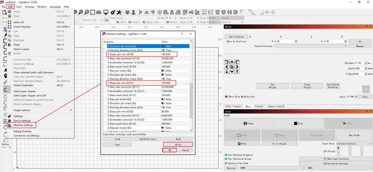
Figure 61
3. Restore the Factory Settings
If the above steps do not resolve the issue, refer to the K2 Pro Factory Reset Video and follow the steps below:
① AtomStack Studio
- Click Settings in the navigation bar and locate Version: V*.*.* in the Settings window.
- Click the number after the version number more than 7 times consecutively. The Serial Port Log developer mode option will appear in the menu bar.
- Click Serial Port Log to open the interface. A series of execution codes will be displayed in the code window.
- Click Reset in the lower-right corner of the interface. If the console indicates that the reset is complete and displays “OK” at the end, the reset is complete.
- Click Close in the upper-right corner to exit the interface.
② LightBurn
Select Console, enter $RST=* in the code field, and click Send, as shown in Figure 62.
Figure 62
If none of the above steps resolves the issue, provide the following information to customer service:
- Troubleshooting video: Include the circle engraving process, the condition of each axis, and inspection of the timing pulleys and timing belts.
- Description of the troubleshooting steps performed and the results.
- Screenshot of the firmware version.
- Photo of the machine Serial Number, as shown in Figure 63.
Figure 63
¶ Engraved Output Is Reversed or Mirrored
Follow the steps below to troubleshoot the issue one by one:
1. Confirm That the Movement Direction Is Correct
Click the direction control buttons in the software and check whether the movement direction of each axis is correct. If the movement direction is reversed, skip to Step (3) to restore the factory settings, or modify the corresponding axis's $3 value in Machine Settings in LightBurn, as shown in Figure 64.
Figure 64
2. Confirm That No Conveyor or Rotary Device Is Being Used
If a conveyor or rotary device is being used, check the following:
① Check whether the device is positioned correctly.
- Note that the connector for the conveyor is located at the front of the laser engraver.
- The motor of the rotary device should be on the right side.
② Check whether the mirroring function is enabled in the software.
- If it is enabled, disable it.
- If it is disabled, enable it.
AtomStack Studio: The mirror settings are shown in Figure 65.
LightBurn: The mirror settings are shown in Figure 66.
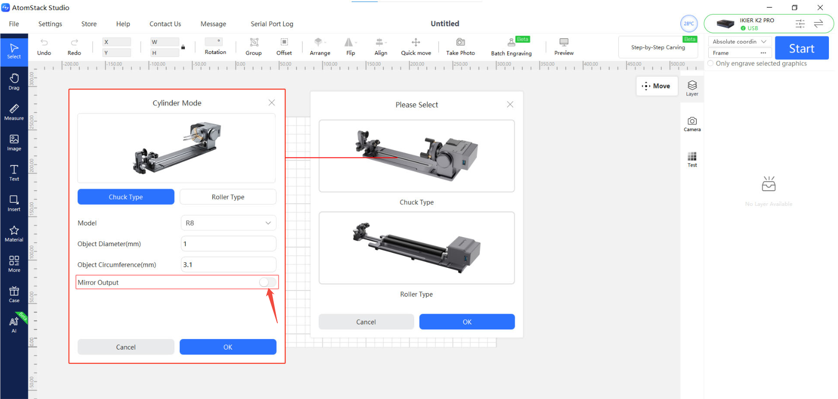
Figure 65
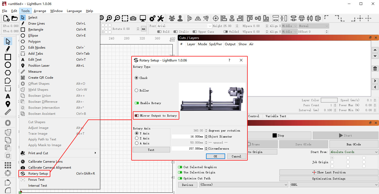
Figure 66
3. Restore the Factory Settings
If the above steps do not resolve the issue, refer to the K2 Pro Factory Reset Video and follow the steps below:
① AtomStack Studio
- Click Settings in the navigation bar and locate Version: V*.*.* in the Settings window.
- Click the number after the version number more than 7 times consecutively. The Serial Port Log developer mode option will appear in the menu bar.
- Click Serial Port Log to open the interface. A series of execution codes will be displayed in the code window.
- Click Reset in the lower-right corner of the interface. If the console indicates that the reset is complete and displays “OK” at the end, the reset is complete.
- Click Close in the upper-right corner to exit the interface.
② LightBurn
Select Console, enter $RST=* in the code field, and click Send, as shown in Figure 67.
Figure 67
4. Contact Customer Service
If none of the above steps resolves the issue, provide the following information to customer service:
- Troubleshooting video: Include the circle engraving process and the movement direction test.
- Description of the troubleshooting steps performed and the results.
- Screenshot of the firmware version.
- Photo of the machine Serial Number, as shown in Figure 68.
Figure 68
¶ The Red Crosshair Position Does Not Coincide with the Laser Engraving Position
Refer to the K2 Pro Laser Crosshair Calibration Video and follow the steps below to troubleshoot the issue:
1. Operation Steps in the Computer Software
① Home the Machine
After connecting the machine successfully, home the machine first to ensure that the coordinates are reset to zero.
② Enter the Calibration Interface
- Open Device Information in the upper-right corner of the software and confirm that Red Crosshair Positioning is displayed under Positioning Mode.
- Click the Calibrate button next to Red Crosshair Positioning Calibration to enter the crosshair calibration interface.
③ Frame to Confirm the Area
Click Frame to confirm that the calibration pattern is within the engraving area.
④ Start Engraving
Click Start. The machine will engrave a cross-shaped pattern as a calibration reference.
⑤ Align the Crosshairs
According to the prompt, use the direction control buttons to adjust the position of the laser head until the red crosshair is completely aligned with the engraved cross-shaped pattern.
If the movement distance for a single adjustment is too large, manually adjust the step value (the distance moved each time) for more precise control.
⑥ Complete Calibration
Click Complete. The system will save the calibration result automatically, completing the calibration.
2. Operation Steps in the Mobile App
① Enter the Calibration Interface
Open the app home page and tap Settings below the machine model name to enter the device settings interface.
② Mark the Cross
Tap Red Crosshair Positioning Calibration. In the Mark Current Position pop-up window, tap the center of the circle. The machine will automatically engrave a cross-shaped pattern as a calibration reference.
③ Align the Red Crosshair
After engraving is complete, follow the prompt and use the direction control buttons to move the laser head until the red crosshair is completely aligned with the engraved cross-shaped pattern.
If the movement distance for a single adjustment is too large, manually adjust the step value (the distance moved each time) for more precise control.
④ Complete Calibration
After confirming that the crosshair is completely aligned with the engraved cross-shaped pattern, click Complete. The system will automatically save the calibration result, completing the calibration.
3. If an Abnormality Occurs During Calibration or the Calibration Is Still Inaccurate After Completion
Refer to the K2 Pro Factory Reset Video and follow the steps below:
① AtomStack Studio
- Click Settings in the navigation bar and locate Version: V*.*.* in the Settings window.
- Click the number after the version number more than 7 times consecutively. The Serial Port Log developer mode option will appear in the menu bar.
- Click Serial Port Log to open the interface. A series of execution codes will be displayed in the code window.
- Click Reset in the lower-right corner of the interface. If the console indicates that the reset is complete and displays “OK” at the end, the reset is complete.
- Click Close in the upper-right corner to exit the interface.
② LightBurn
Select Console, enter $RST=* in the code field, and click Send, as shown in Figure 69.
Figure 69
¶ Camera Not Working Properly
Follow the steps below to troubleshoot the issue one by one:
1. Confirm the Connection Method
A Type-C cable must be used to connect the machine for the camera function to work properly. If the machine is connected via Wi-Fi, the camera may fail to capture images or the captured images may be abnormal.
2. Confirm That the Required Permissions Are Enabled
First, use the camera app built into the computer to test whether the camera can capture images properly:
- If the camera can capture images normally, skip directly to Step (6).
- If the camera cannot capture images, open Device Manager and check whether the camera is restricted or disabled. If so, remove the restriction and enable the required permissions, as shown in Figure 70.
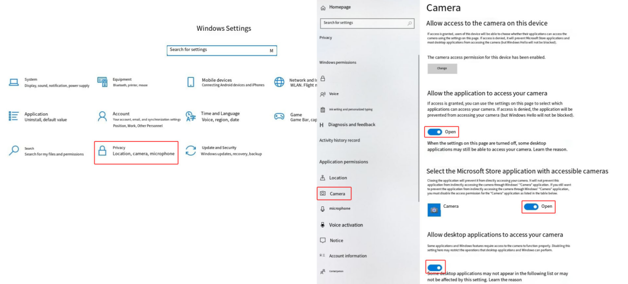
Figure 70
3. Confirm the Coordinate Mode
When using the camera function, Absolute Coordinates mode must be selected.
4. Confirm That the Connection Cable Is Properly Connected
Refer to the K2 Pro Camera Connection Cable Replacement Video and check the following:
- Check whether the camera cable is loose.
- Check whether the cable connection on the mainboard is loose.
- Check whether the connection cable is damaged.
You can disconnect the cable and reconnect it, then test again.
5. Change the Computer's USB Port
Try connecting the cable to a different USB port on the computer. If you are using a desktop computer, it is recommended to use a USB port on the back of the computer case.
6. Clear the AtomStack Studio Cache
If the computer's built-in camera application can capture images normally, but AtomStack Studio cannot capture images or the captured images are very blurry, perform the following steps according to the operating system:
- Windows: Locate the “atomstack” folder under
C:\Users\Administrator\Documents\, delete it, then download and install the latest version of the client again. - macOS: Delete the folder at
/Users/"User Machine Name"/Library/Containers/com.atomstack/Data, then download and install the latest version of the client again.
Some users may use a different username. If the folder cannot be found at the above path, search for the “atomstack” folder.
7. Contact Customer Service
If you identify a problem during troubleshooting but cannot resolve it yourself, or if you are still unable to determine the cause of the fault, provide the following information to customer service:
- Troubleshooting video: Include the camera alignment process and the computer's built-in camera app test.
- Description of the troubleshooting steps performed and the results.
- Photo of the machine Serial Number, as shown in Figure 71.
Figure 71
8. Accessory Replacement References
- If the camera connection cable needs to be replaced, refer to the K2 Pro Camera Connection Cable Replacement Video.
- If the camera needs to be replaced, refer to the K2 Pro Camera Replacement Video.
¶ Large Errors When Using the Camera
Please follow the steps below to troubleshoot the issue one by one:
1. Confirm that the coordinate mode is set to “Absolute Coordinates”
When using the camera function, the coordinate mode must be set to “Absolute Coordinates”.
2. Check the operating environment
The camera should be used in a well-lit environment, and the enclosure door must be closed.
Check whether the LED light strips inside the enclosure are lit properly.
3. Confirm that the camera has been calibrated
- If you are using AtomStack Studio, you only need to perform camera alignment.
- If you are using LightBurn, perform camera calibration and alignment according to the Camera Usage Guide section.
During calibration or alignment, a capture value will be displayed. The lower the capture value, the higher the accuracy.
4. Confirm the material height
The material height used during camera alignment or calibration serves as the accuracy reference. If the current engraving material differs significantly in height from the material used during calibration, camera accuracy will be significantly reduced. It is recommended to perform alignment or calibration again at the height of the current material before use.
5. Confirm that the material is not placed at the edge of the camera's field of view
The center of the camera's capture range provides the highest accuracy, while accuracy is relatively lower at the edges. It is recommended to place the material in the central area of the camera's field of view and avoid placing it near the edges.
6. Confirm that the camera lens is clean
If the camera image appears blurry, check whether the lens is dirty. If there is any dirt or debris, use anhydrous ethanol and a lint-free cloth to gently wipe the surface of the camera lens.
7. Contact Customer Support
If the issue cannot be resolved after completing the above steps, provide the following information when contacting Customer Support:
- Troubleshooting video: Include the calibration or alignment procedure, the actual operating environment, and a comparison of the current material thickness with the material height used during calibration or alignment.
- Completed troubleshooting steps and results.
- Photo of the machine Serial Number, as shown in Figure 72.
Figure 72
8. Accessory replacement reference
- If the camera needs to be replaced, refer to the K2 Pro Camera Replacement Video.
¶ Abnormal X-Axis or Y-Axis Movement
Please follow the steps below to troubleshoot the issue one by one:
1. Confirm that the fixing blocks have been removed
The X-axis is locked during shipment. After receiving the machine, remove the two fixing modules used to secure both ends of the X-axis according to the user manual to ensure that the X-axis can slide freely.
2. Confirm the movement direction
Click the directional movement buttons in the software and check whether the movement direction of each axis is abnormal.
- If the movement direction is reversed, the issue can be resolved by restoring the factory settings, or by modifying the corresponding axis
$3value in “Machine Settings” in LightBurn, as shown in Figure 73. - If the axis cannot move, moves intermittently, or exhibits other abnormalities, continue troubleshooting with the following steps.
Figure 73
3. Check the motor cables
According to the K2 Pro X/Y/Z-Axis Motor Replacement Video, check whether the motor cables are loose or damaged. If no abnormalities are found, disconnect and reconnect the cables, then test again.
4. Check the mainboard cables
According to the K2 Pro Mainboard Replacement Video, check whether any cables on the mainboard are loose or disconnected.
5. Check the eccentric nuts
Manually move the X-axis and Y-axis. If you feel significant resistance during movement, refer to the K2 Pro Mechanical Structure Adjustment Video to check whether the eccentric nuts are too tight. If they are too tight, loosen them appropriately.
6. Check the profiles and linear shafts
Carefully inspect the linear shaft guides and profiles of the X-axis and Y-axis for damage, and check whether there are signs of friction on the linear shaft surfaces or whether the surfaces are excessively dry.
- If the surfaces are dry: Clean the linear shafts according to the K2 Pro Enclosure Interior Cleaning Video, then evenly apply lubricating grease.
- If any damage is found: Take clear photos and contact Customer Support.
7. Restore the factory settings
If the above steps do not resolve the issue, refer to the K2 Pro Factory Reset Video and follow the steps below:
① AtomStack Studio
- Click the “Settings” menu in the navigation bar and locate “Version: V*.*.*” in the Settings window.
- Click the number after the version number 7 or more times consecutively. The “Serial Port Log” developer mode option will appear in the menu bar.
- Click “Serial Port Log” to enter the interface. A series of execution codes will be displayed in the code box.
- Click “Reset” in the lower-right corner of the interface. If the console indicates that the reset is complete and “OK” is displayed at the end, the reset has been completed.
- Click “close” in the upper-right corner of the interface to exit.
② LightBurn
Select the “Console” and enter $RST=* in the code box, then click Send, as shown in Figure 74.
Figure 74
8. Contact Customer Support
If you identify an issue during troubleshooting but cannot resolve it yourself, or if you are unable to determine the cause of the fault, provide the following information when contacting Customer Support:
- Troubleshooting video: Show the abnormal movement.
- Completed troubleshooting steps and results.
- Photo of the machine Serial Number, as shown in Figure 75.
Figure 75
9. Accessory replacement reference
- If the mainboard needs to be replaced, refer to the K2 Pro Mainboard Replacement Video.
- If a motor needs to be replaced, refer to the K2 Pro X/Y/Z-Axis Motor Replacement Video.
- If you need to replace the X-axis/Y-axis motor cable, please refer to the K2 Pro Connection Cable Replacement Video.
¶ Engraved Lines Are Too Thick
Please follow the steps below to troubleshoot the issue one by one:
1. Confirm the focal distance
After placing a new material, perform autofocus first. You can also manually adjust the focal distance. The optimal fixed focal distance is 40 mm.
2. Confirm the material
Check whether the material being engraved is thermoplastic (melts when exposed to high temperatures). If the material is thermoplastic, molten material may adhere to the cut surface during laser processing, resulting in rough edges and slag buildup. In some cases, molten material may also splatter and contaminate the lens.
3. Check the protective window and focusing lens
Refer to the K2 Pro Laser Cleaning Video to check whether the protective window and focusing lens are damaged or dirty.
- If they are dirty: Clean them according to the Laser Protective Window or Focusing Lens Contamination section.
- If they are damaged: Provide clear photos and contact Customer Support.
4. Confirm that air assist is enabled
Air assist can effectively improve engraving and cutting results. Confirm that air assist is enabled.
5. Check the laser spot
Raise the Z-axis to its highest position and use the laser firing function to check whether the laser spot is abnormal. You can take a clear photo and provide it to Customer Support for evaluation.
6. Contact Customer Support
If you identify an issue during troubleshooting but cannot resolve it yourself, or if you are unable to determine the cause of the fault, provide the following information when contacting Customer Support:
- Troubleshooting video: Show the engraving lines during processing and the final result, as well as the protective window and focusing lens.
- Completed troubleshooting steps and results.
- Photo of the machine Serial Number, as shown in Figure 76.
Figure 76
7. Accessory replacement reference
- If the protective window needs to be replaced, refer to the K2 Pro Laser Cleaning Video.
¶ Cut Lines Are Yellow or Black, and the Material Cannot Be Cut Through
Please follow the steps below to troubleshoot the issue one by one:
1. Confirm the material batch
Materials from different batches may produce different cutting results due to variations in the manufacturing process. It is recommended to:
- Use materials from the same batch for comparison testing.
- Cut A4 paper to determine whether the laser power has significantly decreased.
The recommended parameters for cutting A4 paper are as follows:
Use 40% power and a speed of 5000 mm/min.
2. Confirm the focal distance
After placing a new material, perform autofocus first. You can also manually adjust the focal distance. The optimal focal distance is 40 mm.
3. Check the parameter settings in the software
Different materials require different processing parameters. Refer to the parameter table to confirm that the power, speed, and speed unit are set correctly.
How to view the parameter table:
- Scan the QR code on the machine to view it.
- Check the included USB flash drive.
- Contact Customer Support.
4. Confirm that air assist is enabled
Air assist can effectively improve engraving and cutting results. Confirm that air assist is enabled.
5. Check that the air guide is not obstructed
Refer to the Laser Protective Window or Focusing Lens Contamination section to remove and inspect the air guide. Confirm that it is free of dirt and is not misaligned or obstructing the laser beam.
6. Check the protective window and focusing lens
Refer to the K2 Pro Laser Cleaning Video to check whether the protective window and focusing lens are damaged or dirty.
- If they are dirty: Clean them according to the Laser Protective Window or Focusing Lens Contamination section.
- If they are damaged: Provide clear photos and contact Customer Support.
7. Check the S-Value Max setting (LightBurn)
The S-Value Max must remain at 1000 (as shown in Figure 77). Do not change this value, as doing so may affect laser power and service life.
Figure 77
8. Confirm the power supply voltage
Insufficient voltage or current will directly affect laser power.
- Measure the adapter: Set the multimeter to DC voltage mode and measure the adapter output. It should be 24 V.
- Measure the laser cable: Disconnect the laser cable, run a cutting program at 100% power and a speed of 1 mm/min, and use a multimeter in DC voltage mode to measure whether the voltage between pins 2 and 3 is 24 V and the voltage between pins 4 and 5 is 5 V, as shown in Figure 78. Refer to the K2 Pro Laser Cable Voltage Measurement Video for the measurement procedure.
Figure 78
9. Check the laser spot
Raise the Z-axis to its highest position and use the laser firing function to check whether the laser spot is abnormal. You can take a clear photo and provide it to Customer Support for evaluation.
10. Contact Customer Support
If you identify an issue during troubleshooting but cannot resolve it yourself, or if you are unable to determine the cause of the fault, provide the following information when contacting Customer Support:
- Troubleshooting video: Show the engraving lines during processing and the final result, as well as the condition of the protective window and focusing lens.
- Completed troubleshooting steps and results.
- Photo of the machine Serial Number, as shown in Figure 79.
Figure 79
11. Accessory replacement reference
- If the protective window needs to be replaced, refer to the K2 Pro Laser Cleaning Video.
¶ Engraved Lines Are Discontinuous at Corners or Start/End Points (Not Closed)
Please follow the steps below to troubleshoot the issue one by one:
1. Check the software parameters
Refer to the recommended parameter table and check whether the current settings are appropriate. You can try increasing the power or reducing the speed slightly, then test whether the line closure improves.
2. Enable Constant Power
Enable “Constant Power” mode in the software and test whether this resolves the issue.
3. Adjust the minimum power value
Refer to the K2 Pro Minimum Power Adjustment Video and follow the steps below:
Discontinuous or unclosed lines are usually related to the laser's minimum power value ($31) being set too low. Adjust it as follows:
① AtomStack Studio:
- Open the Settings menu and left-click the software version number more than 7 consecutive times to activate Developer Mode.
- Click “Serial Port Log” in the menu bar to open the console.
- Enter
$31=*in the code box and send the command. The * represents the value to be tested. Gradually increase the value until the line is closed. For example, if the line cannot be closed when$31is set to 0, send$31=10. If the line is still not closed, increase the value and send$31=20. Continue increasing the value until the line is closed.
② LightBurn:
- Click “Edit” and select “Machine Settings”, then locate
$31. - Gradually increase its value, then click “Write” → “OK” to save the setting.
- Repeat the process, continuously increasing the
$31value until the line is closed.
4. Restore the factory settings
If the above steps do not resolve the issue, refer to the K2 Pro Factory Reset Video and follow the steps below:
① AtomStack Studio
- Click the “Settings” menu in the navigation bar and locate “Version: V*.*.*” in the Settings window.
- Click the number after the version number 7 or more times consecutively. The “Serial Port Log” developer mode option will appear in the menu bar.
- Click “Serial Port Log” to enter the interface. A series of execution codes will be displayed in the code box.
- Click “Reset” in the lower-right corner of the interface. If the console indicates that the reset is complete and “OK” is displayed at the end, the reset has been completed.
- Click “close” in the upper-right corner of the interface to exit.
② LightBurn
Select the “Console” and enter $RST=* in the code box, then click Send, as shown in Figure 80.
Figure 80
5. Contact Customer Support
If you identify an issue during troubleshooting but cannot resolve it yourself, or if you are unable to determine the cause of the fault, provide the following information when contacting Customer Support:
- Troubleshooting video: Show the cutting lines during processing and the final result, as well as the condition of the protective window and focusing lens.
- Completed troubleshooting steps and results.
- Photo of the machine Serial Number, as shown in Figure 81.
Figure 81
¶ Enclosure LED Light Strip Malfunction
Please follow the steps below to troubleshoot the issue one by one:
1. Confirm that the LED light strip cable is properly connected
Open the enclosure door and check whether the LED light strip cable inside the enclosure is properly connected, as shown in Figure 82. Disconnect and reconnect the cable, then test again.
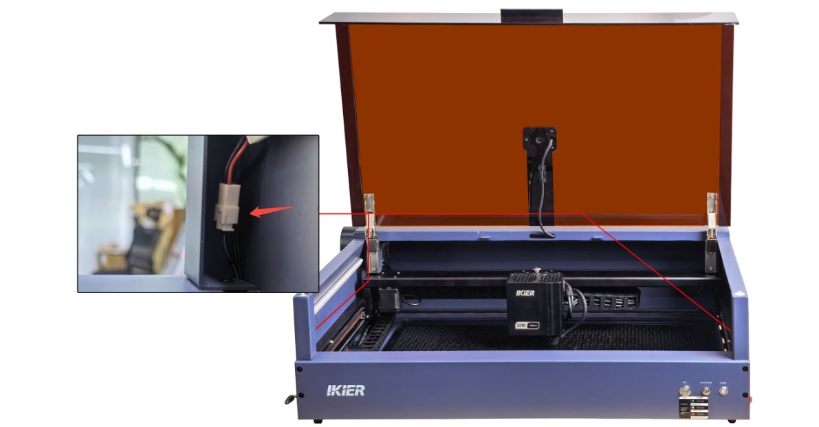
Figure 82
2. Measure the voltage of the LED light strip cable
Disconnect the LED light strip cable and use a multimeter in DC voltage mode to measure whether the cable voltage is approximately 24 V, as shown in Figure 83.
- If the voltage is approximately 24 V, the LED light strip is faulty.
- If the voltage is approximately 0 V, the LED light strip cable is faulty.
- If a multimeter is not available, you can directly power the LED light strip with the adapter for testing. This requires two additional short cables to connect the adapter output to the LED light strip.
Make sure to distinguish between the positive and negative terminals.
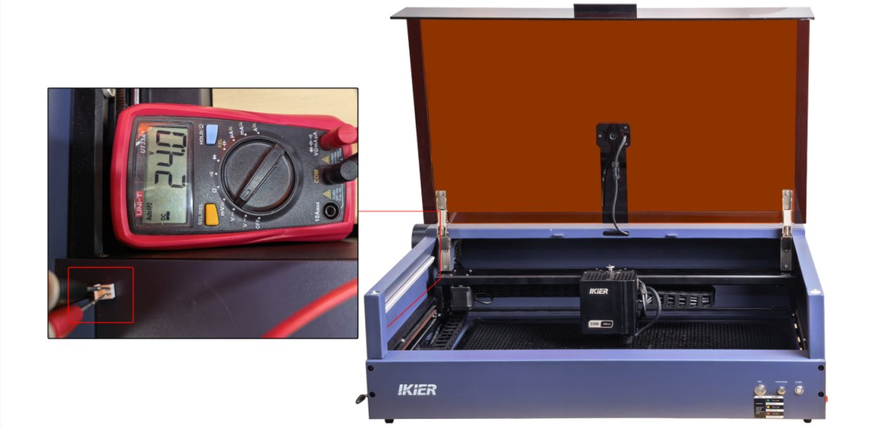
Figure 83
3. Contact Customer Support
If you identify an issue during troubleshooting but cannot resolve it yourself, or if you are unable to determine the cause of the fault, provide the following information when contacting Customer Support:
- Troubleshooting video: Show the LED light strip malfunction and the process of measuring the cable voltage.
- Photo of the machine Serial Number, as shown in Figure 84.
Figure 84
4. Accessory replacement reference
- If the LED light strip needs to be replaced, refer to the K2 Pro LED Light Strip Replacement Video.
¶ Frequent False “ALARM: 12” Flame Alarm Triggers
Please follow the steps below to troubleshoot the issue one by one:
1. Check the operating environment
If the engraving machine is exposed to direct sunlight, the flame alarm may be triggered falsely. Move the machine to another location or block direct sunlight.
2. Confirm the engraving material
If the engraving or cutting material is highly flammable, such as MDF, basswood, cork, or paper, it may easily trigger the flame alarm. You can disable the flame detection function before continuing the process.
Note: After disabling flame detection, the machine must be monitored by a person throughout the entire process to prevent accidents.
3. Check the line density of the engraving file
If the lines in the engraving or cutting file are too dense, the flame alarm may also be triggered falsely. You can increase the speed and increase the number of passes to avoid this issue.
4. Test with another material
Replace the current material with another material, such as plywood, and test whether the flame alarm is triggered again to determine whether the issue is related to the material.
5. Adjust the sensitivity
If the flame alarm is easily triggered when engraving or cutting a particular material, but there is no actual fire, you can appropriately adjust the flame detection sensitivity.
Note that after adjusting the sensitivity, restore the original value before processing other materials.
Note: After adjusting the sensitivity, the machine must be monitored by a person throughout the entire process to prevent accidents.
Follow the steps below to adjust the sensitivity:
① Open the software code console:
- For AtomStack Studio, refer to the K2 Pro Factory Reset Video to enter Developer Mode, then enter the command in the input box at the bottom.
- For LightBurn, directly enter the command in the input box in the “Console”.
② Enter $fire_alarm/threshold_value=* in the input box and send the command. The * represents the value to be tested. The higher the value, the less likely the alarm is to be triggered.
6. Contact Customer Support
If the above steps do not resolve the issue, provide the following information when contacting Customer Support:
- Troubleshooting video: Show the false alarm trigger.
- Completed troubleshooting steps and results.
- Photo of the machine Serial Number, as shown in Figure 85.
Figure 85
7. Accessory replacement reference
- If the flame detection board needs to be replaced, refer to: K2 Pro Laser Flame Alarm Board Replacement Video.
8. Notes
If water is sprayed to extinguish a fire after a flame alarm is triggered, perform the following steps after the fire has been extinguished:
① Dry any residual water:
Start a low-power engraving or cutting program and run it for 5 minutes to use the airflow to dry any water remaining inside the hose.
② Clean the protective window and air guide:
Refer to the K2 Pro Laser Cleaning Video and wipe off any water from the surface of the protective window, the focusing lens (do not remove it), and the inside and outside of the air guide.
After each flame alarm trigger, immediately perform the above drying procedure to prevent water from accumulating and affecting the engraving and cutting performance of the machine.
¶ The “ALARM: 12” Flame Alarm Is Triggered but No Water Is Sprayed
Please follow the steps below to troubleshoot the issue one by one:
1. Confirm That the Water Tank Is Filled
Fill the water tank of the fire-extinguishing air pump with purified water or distilled water.
Note: Do not use tap water for extended periods. Tap water easily produces limescale, which may block the water path.
2. Confirm That the Cables Are Properly Connected
Refer to the Air Assist Usage Guide (with Fire-Extinguishing Function) section to check whether the cable connections are correct. If a multimeter is available, after the flame alarm is triggered (measurement is only valid after the flame alarm has been triggered), use the DC voltage range to measure the voltage of the water pump cable:
- If voltage output is present, the mainboard and the water pump power cable are normal.
- If no voltage output is present, the mainboard or the water pump power cable may be faulty.
3. Check the Water Pump Status
If the water pump cable has voltage input but the water pump still does not work, the water pump may be faulty.
4. Confirm That the Hose Is Properly Connected
Check that the hose is properly connected to the “AIR TUBE” port on the engraver, and confirm that the hose is not bent or blocked.
5. Contact Customer Support
If you identify an issue during troubleshooting but cannot resolve it yourself, or if you are unable to determine the cause of the fault, provide the following information when contacting Customer Support:
- Troubleshooting video: Show that no water is sprayed after the flame alarm is triggered, the water level in the water tank, and the correct connections.
- Completed troubleshooting steps and results.
- Photo of the machine Serial Number, as shown in Figure 86.
Figure 86
6. Accessory Replacement References
- If the water pump needs to be replaced, refer to the K2 Pro Air Pump and Water Pump Replacement Video.
- If the mainboard needs to be replaced, refer to the K2 Pro Mainboard Replacement Video.
¶ Air Assist Not Working
Please follow the steps below to troubleshoot the issue one by one:
1. Confirm That All Connections Are Correct
Refer to the Air Assist Usage Guide (with Fire-Extinguishing Function) section to check whether all cable connections are correct.
2. Confirm That Engraving or Cutting Has Started
The air assist system is controlled by the mainboard and only starts normally after an engraving or cutting program has been started.
3. Confirm That the Air Pump Output Is Enabled in the Software
When setting the engraving parameters, the air assist function must be enabled:
- In AtomStack Studio, enable the “air assist” function below the speed setting on the right, as shown in Figure 87.
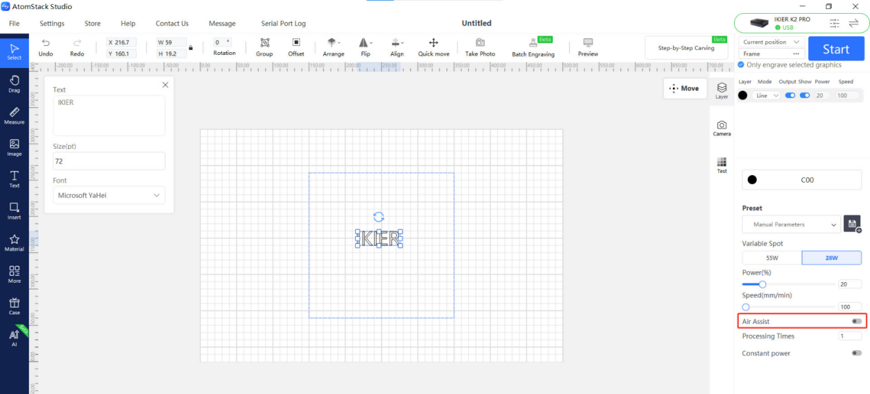
Figure 87
- In LightBurn, go to the parameter settings interface and enable the “air assist” function, as shown in Figure 88.
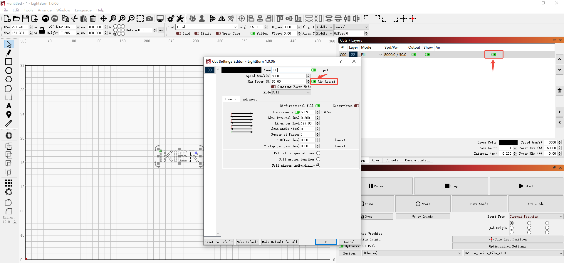
Figure 88
4. Confirm That the Switch Speed Controller Is Turned On
The switch speed controller on the top of the fire-extinguishing air pump is turned on by rotating it clockwise. The airflow can be adjusted according to actual needs.
5. Measure the Voltage of the Air Pump Cable
If a multimeter is available, start an engraving or cutting program first (voltage output is only present at this time), then disconnect the air pump cable from the air pump end and use the DC voltage range to measure the voltage of the air pump cable (as shown in Figure 89):
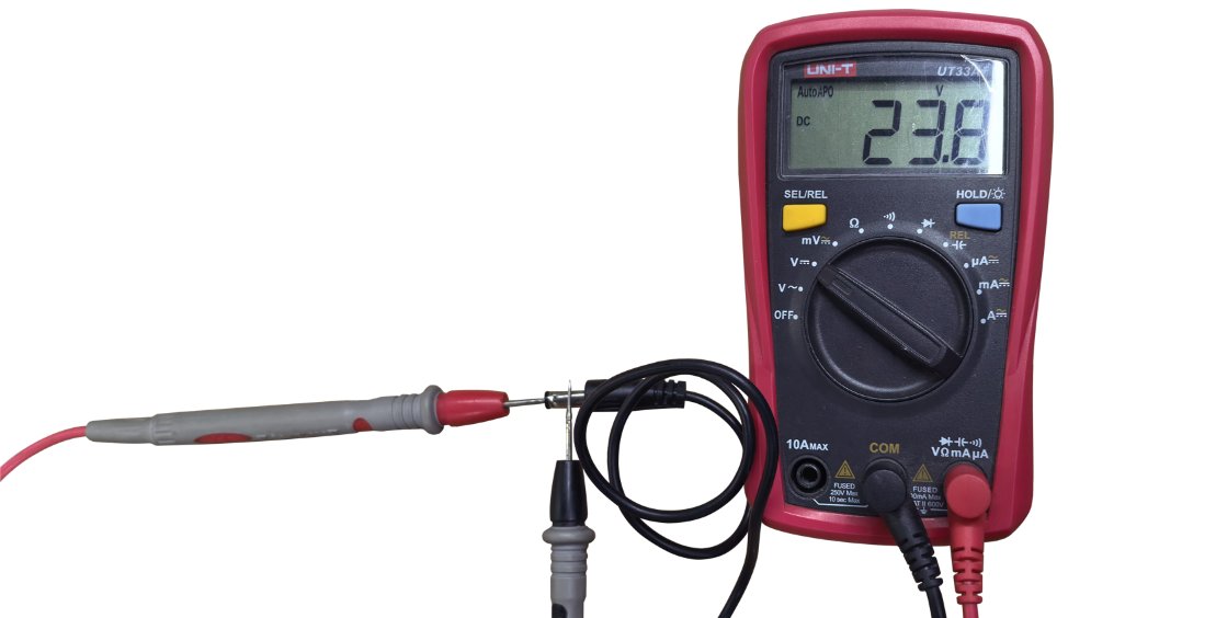
Figure 89
- Voltage output present → The mainboard and the air pump power cable are normal.
- No voltage output → The mainboard or the air pump power cable may be faulty.
6. Check the Air Assist Status
After starting engraving, if there is no airflow or the airflow is very weak, and the air assist hose is not bent and the power supply voltage is normal, touch the surface of the fire-extinguishing air pump by hand:
- Obvious vibration and abnormal noise → The air pump is faulty.
- No vibration, no noise, and no airflow → The switch speed controller is faulty.
7. Contact Customer Support
If you identify an issue during troubleshooting but cannot resolve it yourself, or if you are unable to determine the cause of the fault, provide the following information when contacting Customer Support:
- Troubleshooting video: Show the operating status of the fire-extinguishing air pump (indicating whether there is vibration) and the process of measuring the air pump cable voltage.
- Completed troubleshooting steps and results.
- Photo of the machine Serial Number, as shown in Figure 90.
Figure 90
8. Accessory Replacement References
- If the switch speed controller needs to be replaced, refer to the K2 Pro Switch Speed Controller Replacement Video.
- If the air pump needs to be replaced, refer to the K2 Pro Air Pump and Water Pump Replacement Video.
¶ Water Drips from the Laser Air Guide After Power-On
This phenomenon is usually caused by residual water remaining in the hose after a previous flame alarm triggered water spraying, when the hose was not fully drained. Even if no alarm has been triggered, testing the flame alarm function may also cause water to accumulate inside the hose, resulting in dripping when the machine is powered on and used again.
If dripping occurs, proceed as follows:
① Dry the residual water: Start a low-power engraving or cutting program and run it for 5 minutes to dry the water inside the hose with the airflow.
② Clean the lens and air guide: Refer to the K2 Pro Laser Cleaning Video and wipe dry the surface of the protective window, the focusing lens (do not remove it), and the inside and outside of the air guide.
After each flame alarm is triggered, perform the drying procedure described above immediately to prevent water accumulation from affecting the engraving and cutting performance of the machine.
¶ Laser Power Decreases and the Laser Housing Becomes Very Hot After a Period of Engraving
Please follow the steps below to troubleshoot the issue one by one:
1. Check the Operating Environment Temperature
If the operating environment temperature is high, lower the temperature in time. The recommended ambient temperature range is −10°C to +35°C.
2. Check the Laser Fan
Start an engraving or cutting program and check whether the laser fan rotates normally. If the fan does not rotate, troubleshoot as follows:
① Check the Fan Cable
Refer to the K2 Pro Laser Fan Replacement Video to check whether the cable on the driver board end is properly connected.
② Test the Fan Status
- Prepare two short wires that conduct electricity properly.
- Insert the wires into the fan cable terminals respectively, ensuring that the wires make full contact with the copper wires of the terminals, as shown in Figure 91.
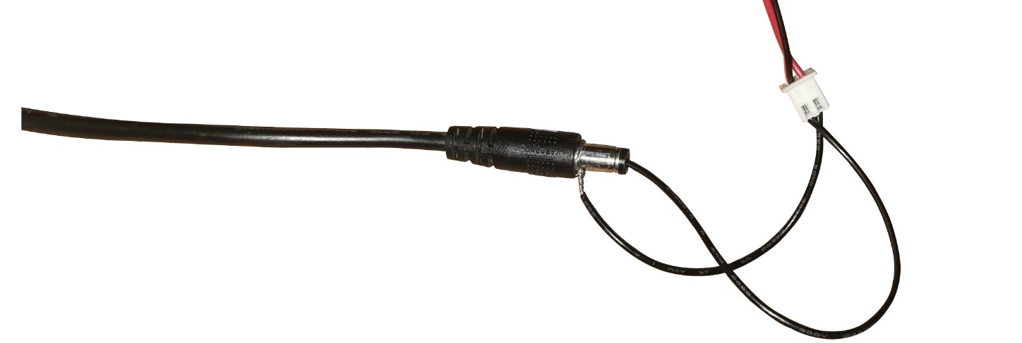
Figure 91
- Connect the two wires to the output of the adapter respectively, so that the adapter supplies power directly to the fan, and check whether the fan rotates normally.
- If the fan rotates normally, the driver board is faulty. If the fan still does not rotate, the fan is faulty.
3. Check the Laser Protective Window and Focusing Lens
Refer to the K2 Pro Laser Cleaning Video to check whether the protective window and focusing lens of the laser module are damaged or dirty.
- If they are dirty: Clean them according to the Laser Protective Window or Focusing Lens Contamination section.
- If they are damaged: Provide clear photos and contact Customer Support.
4. Check the Laser Air Guide
Remove and inspect the air guide according to the Laser Protective Window or Focusing Lens Contamination section, and confirm that the air guide is free of dirt and is not misaligned or obstructing the laser beam.
5. Confirm the Service Life
If the engraver has been used for many years, the thermal grease between the laser tube core and the heat sink may have dried out and failed. It is recommended to replace the thermal grease.
Note: The thermal grease used for computer CPUs can be used (it does not need to be conductive and must not corrode metal).
6. Contact Customer Support
If none of the above steps resolves the issue, provide the following information when contacting Customer Support:
- Troubleshooting video: Show the process of the laser power dropping sharply from normal power, as well as the condition of the protective window and focusing lens.
- Completed troubleshooting steps and results.
- Photo of the laser engraving code on the laser module, as shown in Figure 92.
Figure 92
7. Accessory Replacement References
- If the laser fan needs to be replaced, refer to the K2 Pro Laser Fan Replacement Video.
- If the laser driver board needs to be replaced, refer to the K2 Pro Laser Driver Board Replacement Video.
¶ The Laser Fan Does Not Rotate
Please follow the steps below to troubleshoot the issue one by one:
1. Check the Fan Cable
Refer to the K2 Pro Laser Fan Replacement Video to check whether the cable on the driver board end is properly connected.
2. Separate Power Supply Test
- Prepare two short wires that conduct electricity properly.
- Insert the wires into the fan cable terminals respectively, ensuring that the wires make full contact with the copper wires of the terminals, as shown in Figure 93.
- Connect the two wires to the output of the adapter respectively, so that the adapter supplies power directly to the fan, and check whether the fan rotates normally.
- If the fan rotates normally, the driver board is faulty. If the fan still does not rotate, the fan is faulty.
Figure 93
3. Contact Customer Support
If none of the above steps resolves the issue, provide the following information when contacting Customer Support:
- Troubleshooting video: Show that the laser fan does not rotate.
- Completed troubleshooting steps and results.
- Photo of the laser engraving code on the laser module, as shown in Figure 94.
Figure 94
4. Accessory Replacement References
- If the laser fan needs to be replaced, refer to the K2 Pro Laser Fan Replacement Video.
- If the laser driver board needs to be replaced, refer to the K2 Pro Laser Driver Board Replacement Video.
¶ Smoke Inside the Enclosure Cannot Be Exhausted in Time and Escapes Through the Door Gap
Please follow the steps below to troubleshoot the issue one by one:
1. Check the Fan Status
① Confirm Whether the Fan Rotates
After starting an engraving or cutting program, check whether the enclosure fan rotates normally. If it does not rotate, troubleshoot as follows.
- Check the cable: Refer to the K2 Pro Enclosure Fan Replacement Video to confirm whether the connection cable is properly connected.
- Adapter power supply test: Disconnect the enclosure fan cable and connect the adapter directly to the fan cable (as shown in Figure 95) to test whether the fan rotates. If it rotates normally, the mainboard or the fan power cable is faulty. If it still does not rotate, the fan is faulty.
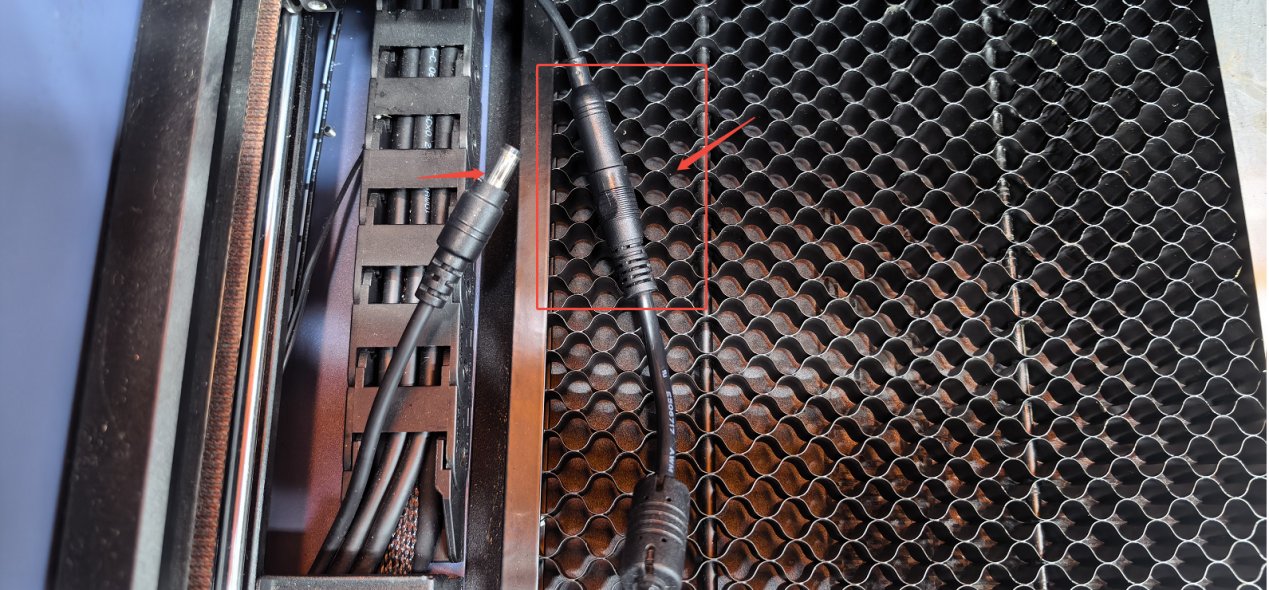
Figure 95
② Check Whether the Fan Blades Are Intact
If the fan rotates, carefully check whether the fan blades are broken or damaged.
Note: Broken or damaged fan blades will seriously affect smoke extraction and cause abnormal noise.
③ Check Whether the Fan Is Dusty
If the fan blades are intact, check whether dust has accumulated on the surface of the blades. If there is dirt, refer to the K2 Pro Enclosure Interior Cleaning Video for cleaning.
2. Check the Exhaust Hose
Check that the exhaust hose is not bent or blocked, and ensure that the exhaust path is clear.
3. Check the Purifier
If a purification device (purifier) is connected, try disconnecting the exhaust hose from the purifier and exhausting directly outdoors, then observe whether the exhaust effect improves:
- If exhaust returns to normal, the problem lies with the purification device (such as a clogged filter or device failure).
- If exhaust is still abnormal, continue checking the enclosure fan or the hose.
4. Contact Customer Support
If none of the above steps resolves the issue, provide the following information when contacting Customer Support:
- Troubleshooting video: Show the smoke exhaust status and the fan status.
- Completed troubleshooting steps and results.
- Photo of the machine Serial Number, as shown in Figure 96.
Figure 96
5. Accessory Replacement References
- If the enclosure fan needs to be replaced, refer to the K2 Pro Enclosure Fan Replacement Video.
- If the mainboard needs to be replaced, refer to the K2 Pro Mainboard Replacement Video.
- If the fan connection cable needs to be replaced, refer to the K2 Pro Connection Cable Replacement Video.
¶ The Image Is Reversed or Mirrored When Using the Rotary Attachment
Please follow the steps below to troubleshoot the issue one by one:
1. Confirm the Placement Orientation
- For the conveyor feeder, note that the cable is at the front of the engraver.
- For the rotary attachment, the motor is on the right side.
2. Check the Mirror Settings
Check whether the mirror output option is selected in the rotary settings of AtomStack Studio or LightBurn, as shown in Figure 97 and Figure 98.
Figure 97
Figure 98
3. Check the Y-Axis Reverse Setting (LightBurn)
In LightBurn or LaserGRBL, select “Machine Settings” under “Edit” in the menu bar, locate “Y Direction pin invert ($3)”. If it is set to true, change it to false; if it is set to false, change it to true. Then click “Write” and click “OK”.
4. Restore the Factory Settings
If none of the above steps resolves the issue, refer to the K2 Pro Factory Reset Video and follow the steps below:
① AtomStack Studio
- Click “Settings” in the navigation bar and locate “Version: V*.*.*” in the Settings window.
- Click the number after the version number more than 7 times consecutively. The “Serial Port Log” developer mode option will appear in the menu bar.
- Click “Serial Port Log” to open the interface. A series of execution codes will be displayed in the code window.
- Click “Reset” in the lower-right corner of the interface. If several lines of reset feedback appear in the code window and “OK” is displayed at the end, the reset is complete.
- Click “Close” in the upper-right corner to exit the interface.
② LightBurn
Select “Console”, enter $RST=* in the code field, and click “Send”, as shown in Figure 99.
Figure 99
5. Contact Customer Support
If none of the above steps resolves the issue, provide the following information when contacting Customer Support:
- Troubleshooting video: Show the engraving status and results.
- Completed troubleshooting steps and results.
- Photo of the machine Serial Number, as shown in Figure 100.
Figure 100
¶ What Should I Do If the Timing Belt Is Broken or Damaged?
Please follow the steps below to troubleshoot the issue one by one:
1. Check Whether the Timing Belt Is Too Tight
Press the timing belt by hand to check whether the belt tension is too high. If it is too tight, refer to the K2 Pro Mechanical Structure Adjustment Video to adjust it.
2. Check Whether the Motor Timing Pulley Is Loose
Move the timing pulley of the X-axis motor and the timing pulleys at both ends of the Y-axis linear shaft by hand to check whether a loose pulley is causing friction.
3. Contact Customer Support
If breakage or damage is found, provide clear photos and a photo of the machine Serial Number (as shown in Figure 101) when contacting Customer Support.
Figure 101
4. Accessory Replacement References
- If the timing belt needs to be replaced, refer to the K2 Pro Timing Belt Replacement Video.
¶ AtomStack Studio Software and Mobile App Updates
1. AtomStack Studio Software Update
Open the software and click “Settings” in the upper-left corner to open the settings interface. At the bottom of the interface, you can view the current version number and the “Check for Updates” button, as shown in Figure 102.
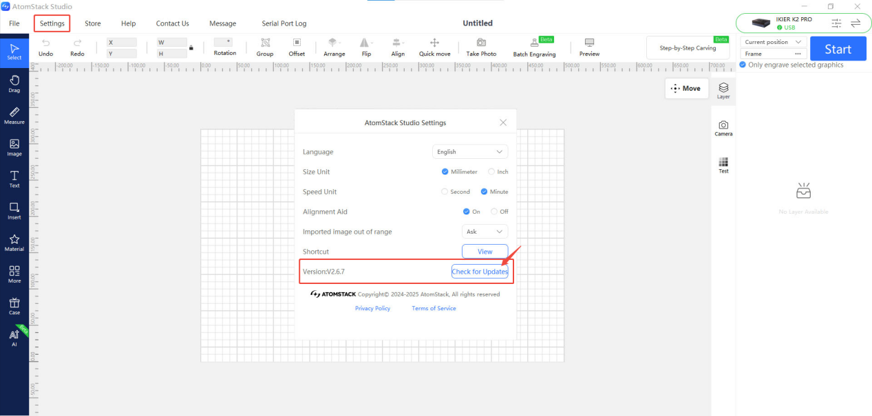
Figure 102
2. AtomStack App Update
Open the mobile app and tap “Profile” in the lower-right corner of the home page, then go to “Settings” → “About ATOMSTACK” to view the current app version. If a new version is available, an update option will be displayed; if not, “Already the latest version” will be displayed, as shown in Figure 103.
Figure 103
¶ Engraver Firmware Update
All firmware update methods require a USB flash drive as the storage medium. Do not power off the machine or remove the USB flash drive during the update process.
1. Update the Firmware via AtomStack Studio
Open the software and connect the laser engraver. Click the “☰” icon in the upper-right corner of the software interface to open the device information interface. At the bottom of the interface, you can view the current firmware version. If an update prompt appears next to the version, click it to update, as shown in Figure 104.
Figure 104
2. Update the Firmware via the AtomStack App
Open the app and connect the engraver, then tap “Settings” below the model name to open the device settings interface. At the bottom of the interface, you can view the current firmware version and the option to update to the new firmware, as shown in Figure 105.
Figure 105
3. Update the Firmware via a USB Flash Drive
If neither of the above methods works, send a screenshot of the current firmware version and a photo of the engraver Serial Number (as shown in Figure 106) to Customer Support to obtain the new firmware. Then follow the steps below to update:
① Remove the USB flash drive and connect it to a computer using a card reader.
② Copy the new firmware file (with the .bin extension) to the root directory of the USB flash drive (do not place it in a folder).
③ Insert the USB flash drive back into the engraver and power it on. The machine will update automatically and emit a “beep-beep” sound.
④ After the beeping stops, restart the engraver.
Figure 106
¶ Alarm Message Descriptions and Handling Methods
| Alarm Message | Description | Solution |
|---|---|---|
| Alarm 1 | A limit switch has been triggered | Check whether a limit switch has been triggered, and pay attention to the size of the engraving file. If the alarm is also triggered at the center point of the engraving area, the limit switch may be faulty. Refer to the section Unable to Operate Properly, with the Message “Limit Switch Triggered” or “Travel Exceeded” for troubleshooting. |
| Alarm 9 | Homing failure | Refer to the Homing Failure section for troubleshooting. |
| Alarm 12 | Flame detection triggered | Check whether the material being engraved or cut has caught fire. If it is a false alarm, refer to the section Frequent False “ALARM: 12” Flame Alarm Triggers. |
| Alarm 13 | Enclosure door open alarm | Please close the enclosure door or close it again before retrying. |